

Measuring device and method for determining the position of an electrically conductive test object
Patent Information
- Authority / Receiving Office
- US · United States
- Patent Type
- Applications(United States)
- Current Assignee / Owner
- MICRO EPSILON MESSTECHNIK GMBH & CO KG
- Publication Date
- 2006-04-20
- Estimated Expiration
- Not applicable · inactive patent
Smart Images
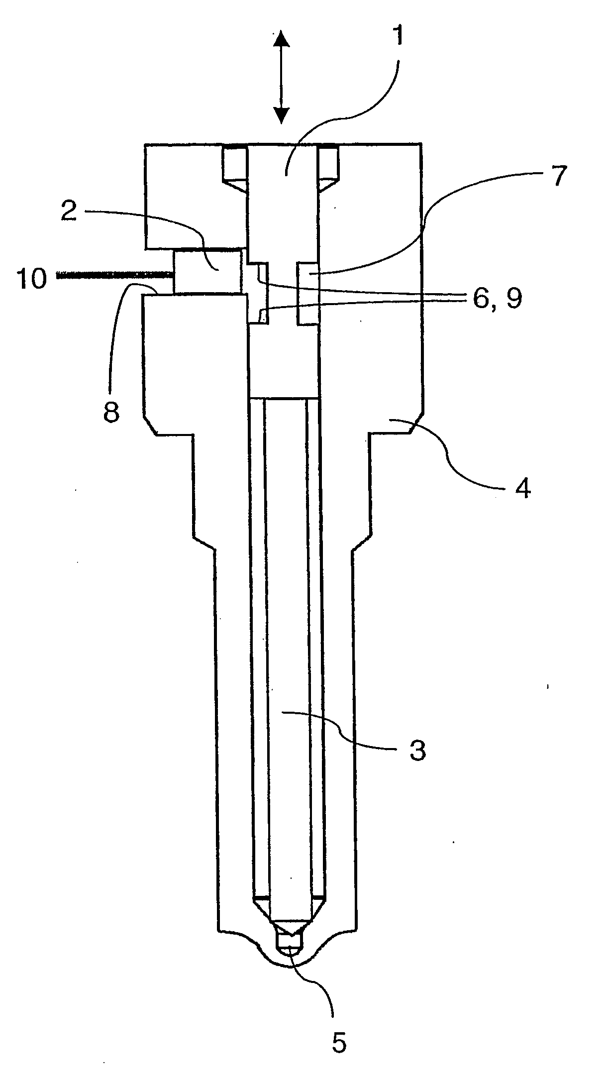
Figure 1 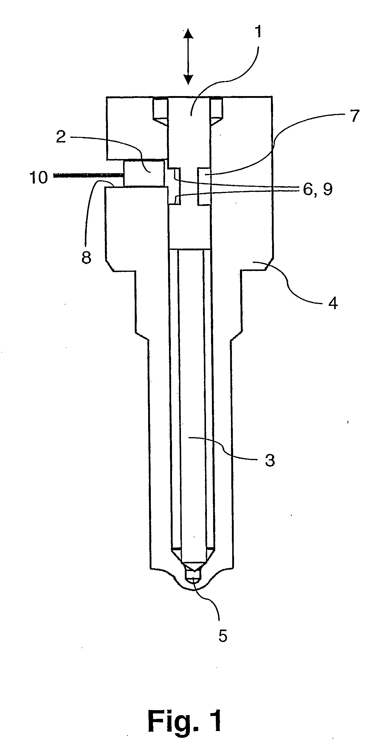
Figure 2 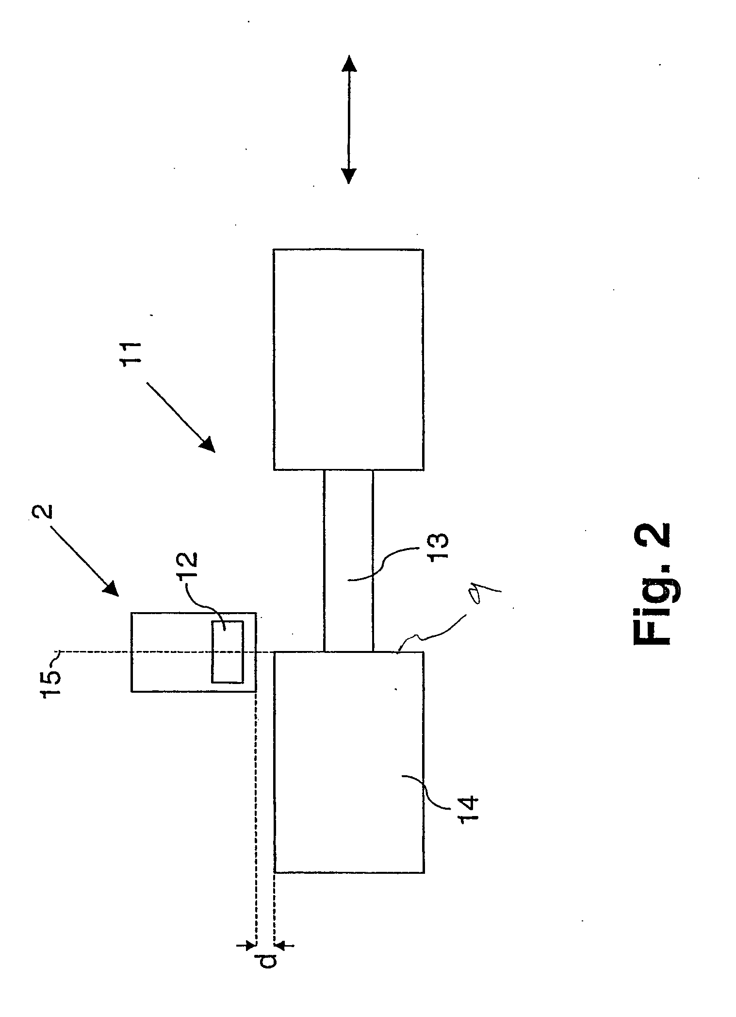
Figure 3
Abstract
Description
CROSS REFERENCE TO RELATED APPLICATION
[0001] The present application is a continuation of international application PCT / DE2004 / 001705, filed 30 Jul., 2004, and which designates the U.S. The disclosure of the referenced application is incorporated herein by reference.BACKGROUND OF THE INVENTION
[0002] The present invention relates to a measuring device and a method for determining the position of an electrically conductive test object with a noncontacting sensor, in particular an eddy current sensor, wherein the test object is adapted for linear reciprocal movement in a predeterminable direction.
[0003] Measuring devices and methods of the type under discussion have been known from practical operation in a great variety of designs and configurations, for example, from DE 101 41 764 A1; U.S. Pat. No. 6,762,922; and U.S. Patent Publication No. 2003 / 0098686. Quite generally, such measuring devices and methods are used to define distances, displacements, or positions relative to any ele...