Magnetoresistive element

a technology of magnetoresistive elements and switching mechanisms, which is applied in the direction of thin material processing, digital storage, instruments, etc., can solve the problems of thermal stability degradation, unfavorable increase in power consumption, and inability to adjust the magnetic memory element's magnetic layer size,

Active Publication Date: 2006-04-20
KIOXIA CORP
View PDF13 Cites 29 Cited by
  • Summary
  • Abstract
  • Description
  • Claims
  • Application Information

AI Technical Summary

Problems solved by technology

Hence, the size of the ferromagnetic layer of the magnetic memory element inevitably decreases.
This leads to an undesirable increase in power consumption.
When the coercive force of the ferromagnetic layer is decreased to reduce power consumption, the thermal stability degrades, and it becomes impossible to store data for a long time.
That is, it is also an important challenge to realize practical use of a bulk magnetic memory having a magnetic memory element which has high thermal stability and is capable of continuously storing data for a long time.
That is, the switching field is small, and flux reversal easily occurs.
In a small magnetic memory element used in a highly integrated magnetic memory, the influence of an edge domain generated at its ends is large, and the change in magnetic structure (magnetization pattern) in flux reversal is complex.
However, the switching field cannot be reduced substantially.
In addition, to fix the edge domain, another structure needs to be added, and it is inappropriate for increasing the density of magnetic memory elements.

Method used


Image

  • Magnetoresistive element
  • Magnetoresistive element
  • Magnetoresistive element

Examples


embodiment

2. EMBODIMENT

[0166] A most preferred embodiment will be described below.

(1) Magnetization State Switching Mechanism

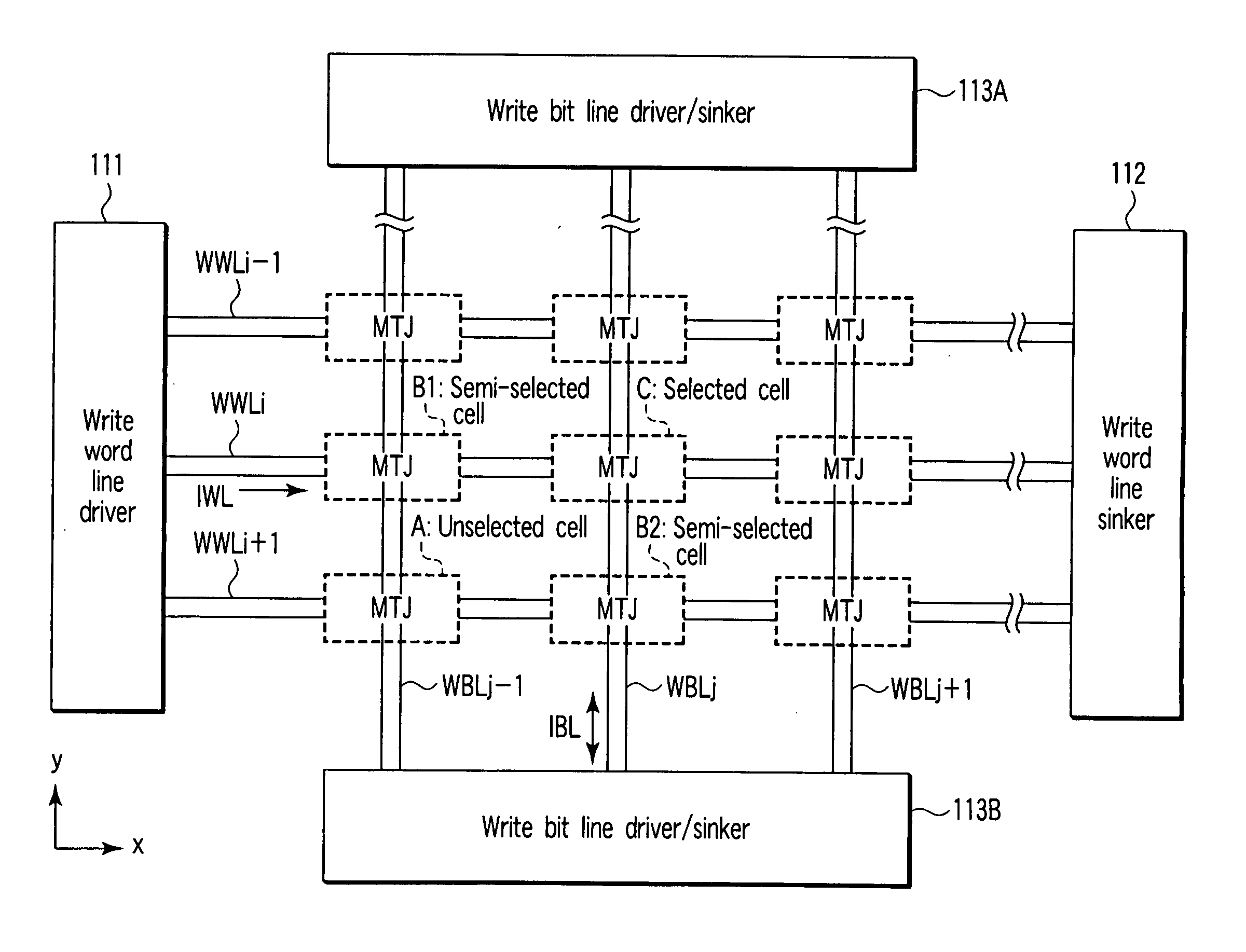
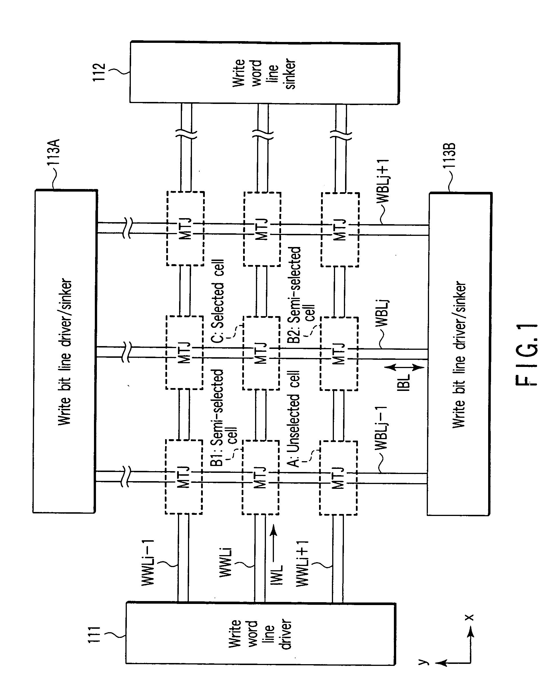
[0167]FIG. 1 shows main parts of a magnetic random access memory to which a magnetization state switching mechanism according to the embodiment of the present invention is applied.

[0168] MTJ elements MTJ are arranged in an array. The shape of the MTJ element MTJ is not particularly limited in executing the magnetization state switching mechanism according to the embodiment of the present invention. This is because the magnetic structure that is easy or hard to cause flux reversal can be controlled by the manner a magnetic field is applied to the magnetoresistive element, and the structure, material, layer thickness, shape, and magnetic anisotropy of the magnetoresistive element.

[0169] Write word lines WWLi−1, WWLi, and WWLi+1 running in the x direction are arranged under the MTJ elements MTJ. A write word line driver 111 is connected to one end of each of the write...

example 5

[0458]FIG. 91 is a plan view showing an MTJ element according to Example 5 of the present invention. The MTJ element according to Example 5 will be described below.

[0459] As shown in FIG. 91, in Example 5, let W be the maximum width of a long portion 10a in the direction of axis of hard magnetization, and A be the maximum width of each of projecting portions 10b and 10c in the direction of axis of hard magnetization. Then, A / W is defined. In this example, an MTJ element 10 having an shape S1 is used.

[0460]FIG. 92 shows the measurement result of the A / W dependence of a magnetic field Hc in the MTJ element according to Example 5 of the present invention. Shapes when A / W=0, 1 / 7, and ½ are illustrated for reference purposes. Hc is normalized by an easy-axis reversal field HcO of the shape with A / W= 1 / 7. The A / W dependence of the magnetic field Hc will be described below.

[0461] As shown in FIG. 92, Hc abruptly decreases near A / W=⅛. However, when A / W>⅛, Hc rarely changes. Hence, when t...

example 6

[0465]FIG. 93 is a plan view showing an MTJ element according to Example 6 of the present invention. The MTJ element according to Example 6 will be described below.

[0466] As shown in FIG. 93, in Example 6, when each of side surfaces f1 and f2 at the easy-axis direction ends of a long portion 10a is formed from a line L2, like the shape S1, an angle φ made by a line L1 in the direction of axis of easy magnetization and the side surfaces f1 and f2 (line L2) is defined.

[0467]FIG. 94A shows the measurement result of the asteroid characteristic of the MTJ element according to Example 6 of the present invention. FIG. 94B shows the measurement result of the φ dependence of a magnetic field Hc in the MTJ element according to Example 6 of the present invention. FIG. 94C shows the φ dependence of the first and second quadrants of the MTJ element according to Example 6 of the present invention. Hc is normalized by Hc of a shape with φ=75° The asteroid characteristic and the φ dependence of H...


PUM


Abstract

A magnetoresistive element includes a first ferromagnetic layer having a first magnetization, the first magnetization having a first pattern when the magnetoresistive element is half-selected during a first data write, a second pattern when the magnetoresistive element is selected during a second data write, and a third pattern of residual magnetization, the first pattern being different from the second and third pattern, a second ferromagnetic layer having a second magnetization, and a nonmagnetic layer arranged between the first ferromagnetic layer and the second ferromagnetic layer and having a tunnel conductance changing dependent on a relative angle between the first magnetization and the second magnetization.

Description

CROSS-REFERENCE TO RELATED APPLICATIONS [0001] This application is based upon and claims the benefit of priority from prior Japanese Patent Applications No. 2004-296455, filed Oct. 8, 2004; No. 2004-296456, filed Oct. 8, 2004; No. 2005-207531, filed Jul. 15, 2005; and No. 2005-207628, filed Jul. 15, 2005, the entire contents of all of which are incorporated herein by reference. BACKGROUND OF THE INVENTION [0002] 1. Field of the Invention [0003] The present invention particularly relates to a switching mechanism of the magnetization state of a magnetoresistive element serving as a data storage medium of a magnetic random access memory. [0004] 2. Description of the Related Art [0005] Various types of solid-state magnetic memories have been proposed conventionally. In recent years, magnetic random access memories using magnetic memory elements which exhibit a giant magnetoresistive effect have been proposed. As a result, the dominating magnetic memory elements presently use a ferromagn...

Claims


Application Information

Patent Timeline
Patent Type & Authority Applications(United States)
IPC IPC(8): G11C11/14
CPCY10T428/1121G11C11/16G11C11/1659G11C11/161G11C11/1673G11C11/1675G11C11/1657H10N50/10
Inventor NAKAYAMA, MASAHIKOKAI, TADASHIKISHI, TATSUYAFUKUZUMI, YOSHIAKINAGASE, TOSHIHIKOIKEGAWA, SUMIOYODA, HIROAKI
Owner KIOXIA CORP
Why Eureka
Try Eureka