Device for supporting and guiding a rotating shaft

a technology for supporting and guiding a rotating shaft, which is applied in the direction of elastic bearings, rigid support of bearings, mechanical apparatuses, etc., can solve the problems of radial vibration and eccentricity of shafts and bearings, significant drop in viscosity, and uncontrollable angular positions of slots in segments, etc., to achieve the effect of eliminating or eliminating, simple, effective and inexpensiv

Active Publication Date: 2006-04-20
SN DETUDE & DE CONSTR DE MOTEURS DAVIATION S N E C M A
View PDF4 Cites 19 Cited by
  • Summary
  • Abstract
  • Description
  • Claims
  • Application Information

AI Technical Summary

Benefits of technology

[0009] A particular object of the invention is to provide a solution to this problem that is simple, effective, and inexpensive, and that was previously unknown in the art, by eliminating or at least greatly reducing the hydrostatic force due to oil leaks localized in the above-mentioned segment slots.
[0012] By distributing these outlet orifices around the periphery of the segment, the resultant of these hydrostatic forces can be substantially canceled, while conserving solely the hydrodynamic forces that provide the desired damping of the orbital movement of the bearing ring. This makes it possible to obtain axially symmetrical behavior for the squeeze film damper and provides better control over the dynamic behavior of the rotor shaft.

Problems solved by technology

Small amounts of rotor shaft unbalance tend to lead to radial vibration and eccentricity of the shaft and its bearings, that must be damped by means of devices for compressing a film of oil (squeeze film dampers) associated with the bearings for supporting and guiding the shaft.
Without cooling, the temperature rise of the oil in the annular space would lead to a significant drop in its viscosity and thus in its ability to damp the orbital movements of the outer ring of the shaft bearing.
The stationary hydrostatic force imparts behavior on the compressed film of oil that is not axially symmetrical and that is uncontrolled since the segments are free to rotate in the grooves of the outer ring of the bearing, which means they can be rotated in random manner by friction, thereby causing the angular positions of the slots in the segments to vary in uncontrolled manner relative to one another and relative to the outer ring of the bearing.
As a result, the behavior of the oil film is not controlled and the radial vibrations and eccentricity of the shafts cannot be damped in completely effective manner.

Method used


Image

  • Device for supporting and guiding a rotating shaft
  • Device for supporting and guiding a rotating shaft
  • Device for supporting and guiding a rotating shaft

Examples


Embodiment Construction

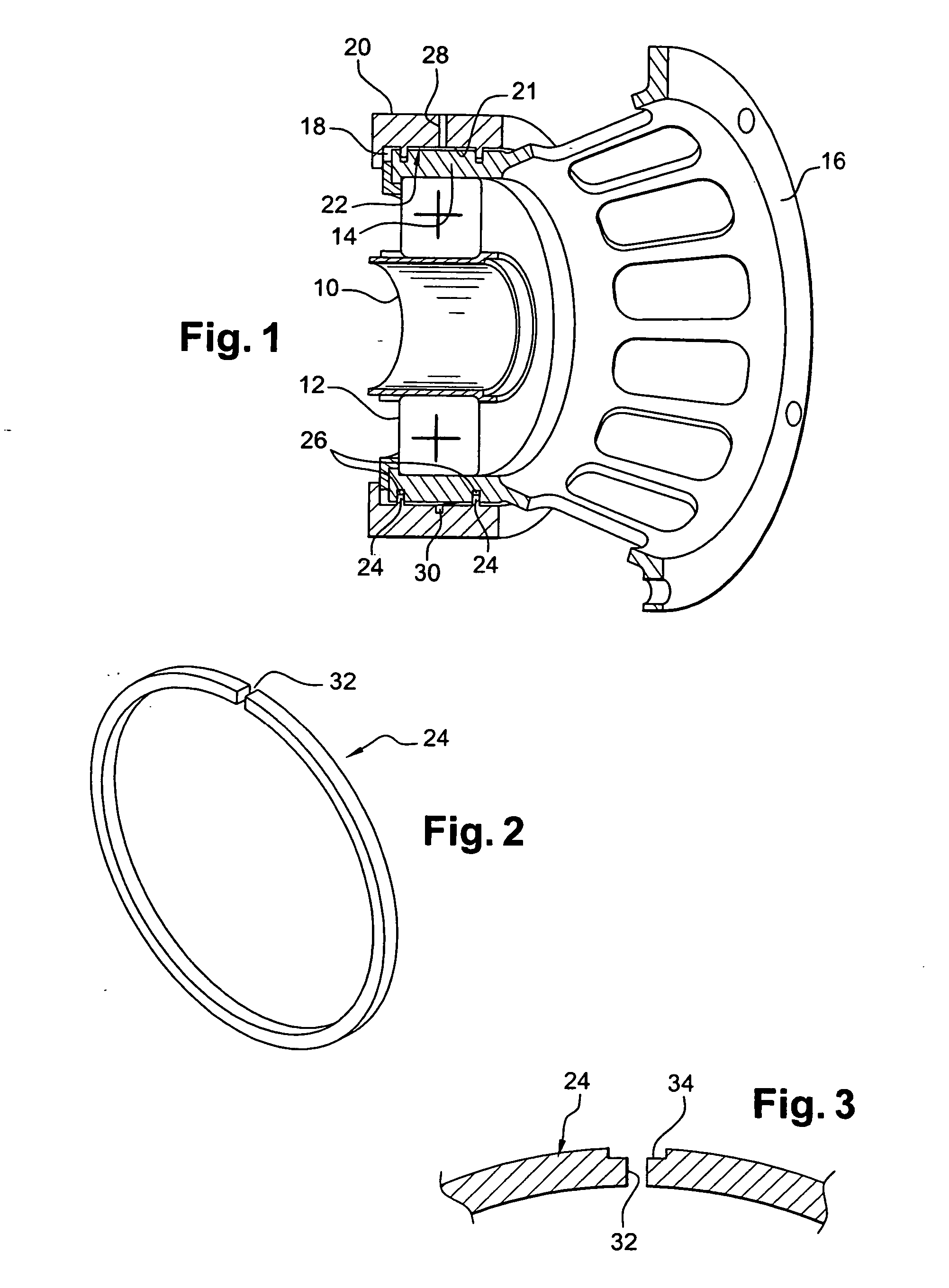
[0028] In FIG. 1, reference 10 designates a rotor shaft of a turbomachine such as an airplane turboprop or turbojet, which shaft is centered and guided in rotation in a bearing 12, e.g. a rolling bearing having an outer ring 14 secured to a squirrel cage 16 and mounted in a cylindrical housing 18 of a case 20 so as to constitute a squeeze film damper around the ring 14.

[0029] An annular space 22 is defined around the ring 14 by the cylindrical surface 21 of the housing 18 and is closed axially by annular sealing elements 24 mounted in annular grooves 26 of the cylindrical outer surface of the ring 14. The annular space 22 is filled with oil fed via an inlet orifice 28 formed by a radial hole through the case 20 and opening out into an annular groove 30 in the cylindrical surface 21 around the ring 14.

[0030] In a variant, the oil can be fed to the annular space 22 via a plurality of radial holes 28 in the case 20, which holes are distributed around the axis rotation of the shaft 10...


PUM


Abstract

A device for supporting and guiding a rotating shaft, in particular a rotor shaft of an airplane turboprop or turbojet, the device comprising an oil squeeze damper around each bearing of the shaft, said damper comprising an annular space surrounding the outer ring of the bearing and defined by annular sealing elements, each having a small number of calibrated oil outlet orifices formed in its outer periphery.

Description

[0001] The invention relates to a device for supporting and guiding a rotating shaft, in particular a rotor shaft in a turbomachine such as an airplane turboprop or turbojet. BACKGROUND OF THE INVENTION [0002] Small amounts of rotor shaft unbalance tend to lead to radial vibration and eccentricity of the shaft and its bearings, that must be damped by means of devices for compressing a film of oil (squeeze film dampers) associated with the bearings for supporting and guiding the shaft. [0003] Each squeeze film damper comprises a housing formed in a support case of the corresponding bearing in which the outer ring of the bearing is mounted with a small amount of radial clearance. An annular space defined around the ring in said housing is filled with oil and is closed axially by annular sealing elements that are free to rotate in annular grooves of the outer ring of the bearing and that co-operate in sealed manner with an inner cylindrical surface of the case. [0004] Oil inlet orifice...

Claims


Application Information

Patent Timeline
Patent Type & Authority Applications(United States)
IPC IPC(8): F16C27/00
CPCF16C27/04F16C2360/23F16C19/26F16C27/045F16C33/581
Inventor LAURANT, FRANCKDEFAYE, CYRIL
Owner SN DETUDE & DE CONSTR DE MOTEURS DAVIATION S N E C M A
Why Eureka
Try Eureka