Turbine shroud segment seal

a technology for gas turbine engines and seals, which is applied in the direction of engine cooling devices, motors, leakage prevention, etc., can solve the problems of increased and unacceptable tolerances between the tip tips of turbine blades, and achieve the effect of accurate tip clearan

Active Publication Date: 2006-04-20
PRATT & WHITNEY CANADA CORP
View PDF26 Cites 68 Cited by
  • Summary
  • Abstract
  • Description
  • Claims
  • Application Information

AI Technical Summary

Benefits of technology

[0009] There is also provided, in accordance with the present invention, a method of assembling a gas turbine engine, comprising the steps of: mounting a turbine shroud segment to a casing; providing a seal between the shroud segment and the casing; and grinding the shroud segment to provide accurate tip clearance, wherein radial support for the shroud segment during grinding is provided substantially by the seal.

Problems solved by technology

This results in increased and unacceptable tolerances between the turbine blade tips and the surrounding turbine shroud segments.

Method used


Image

  • Turbine shroud segment seal
  • Turbine shroud segment seal
  • Turbine shroud segment seal

Examples


Embodiment Construction

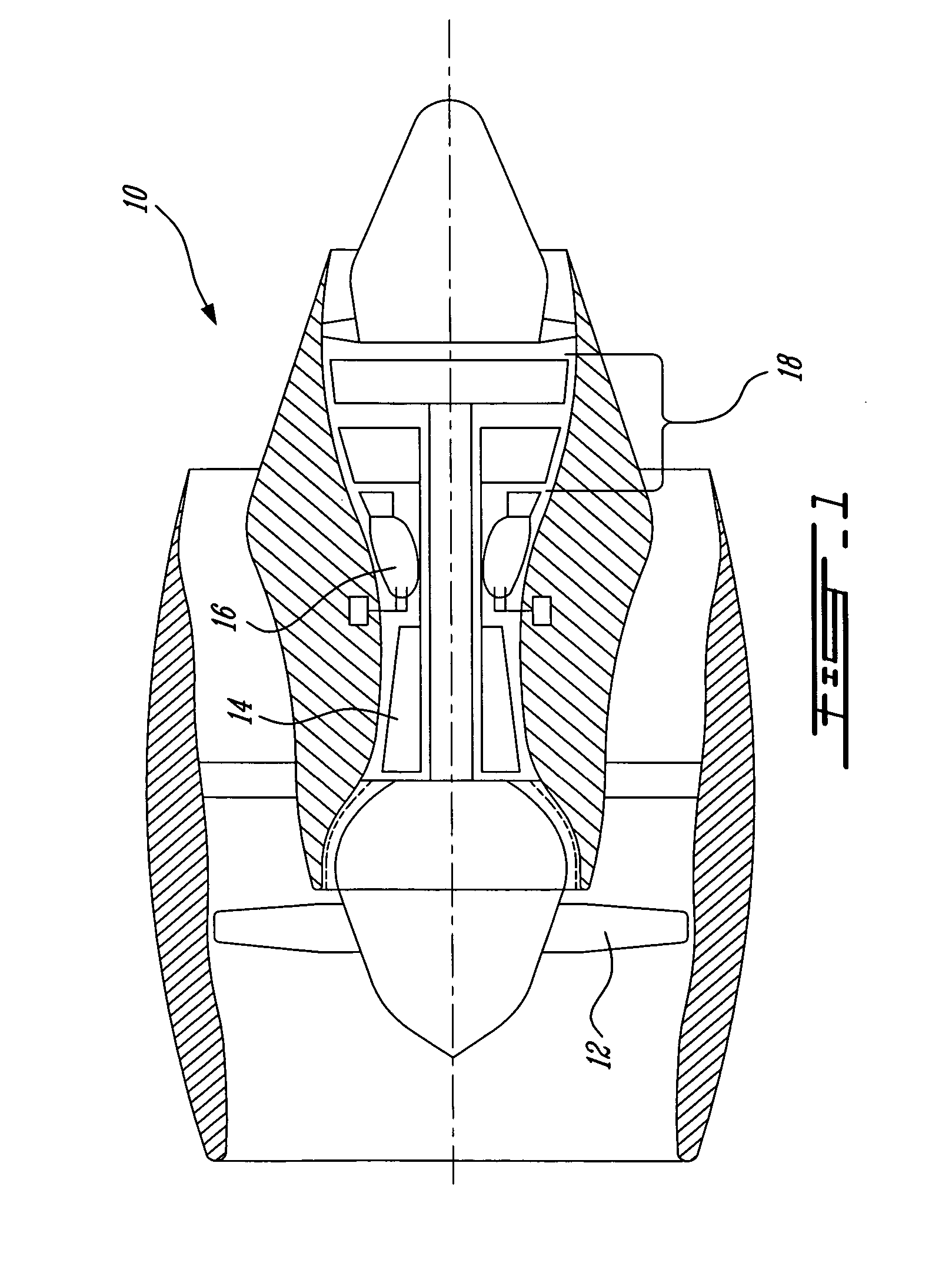
[0016]FIG. 1 illustrates a gas turbine engine 10 of a type preferably provided for use in subsonic flight, generally comprising in serial flow communication a fan 12 through which ambient air is propelled, a multi-stage compressor 14 for pressurizing the air, a combustor 16 in which the compressed air is mixed with fuel and ignited for generating an annular stream of hot combustion gases, and a turbine section 18 for extracting energy from the combustion gases.

[0017] The turbine section 18 may comprise several turbine stages, each of which generally includes a rotatable turbine rotor having a plurality of blades extending therefrom within a surrounding turbine shroud. A plurality of vanes, arranged in an annular configuration, are provided immediately upstream of each turbine rotor.

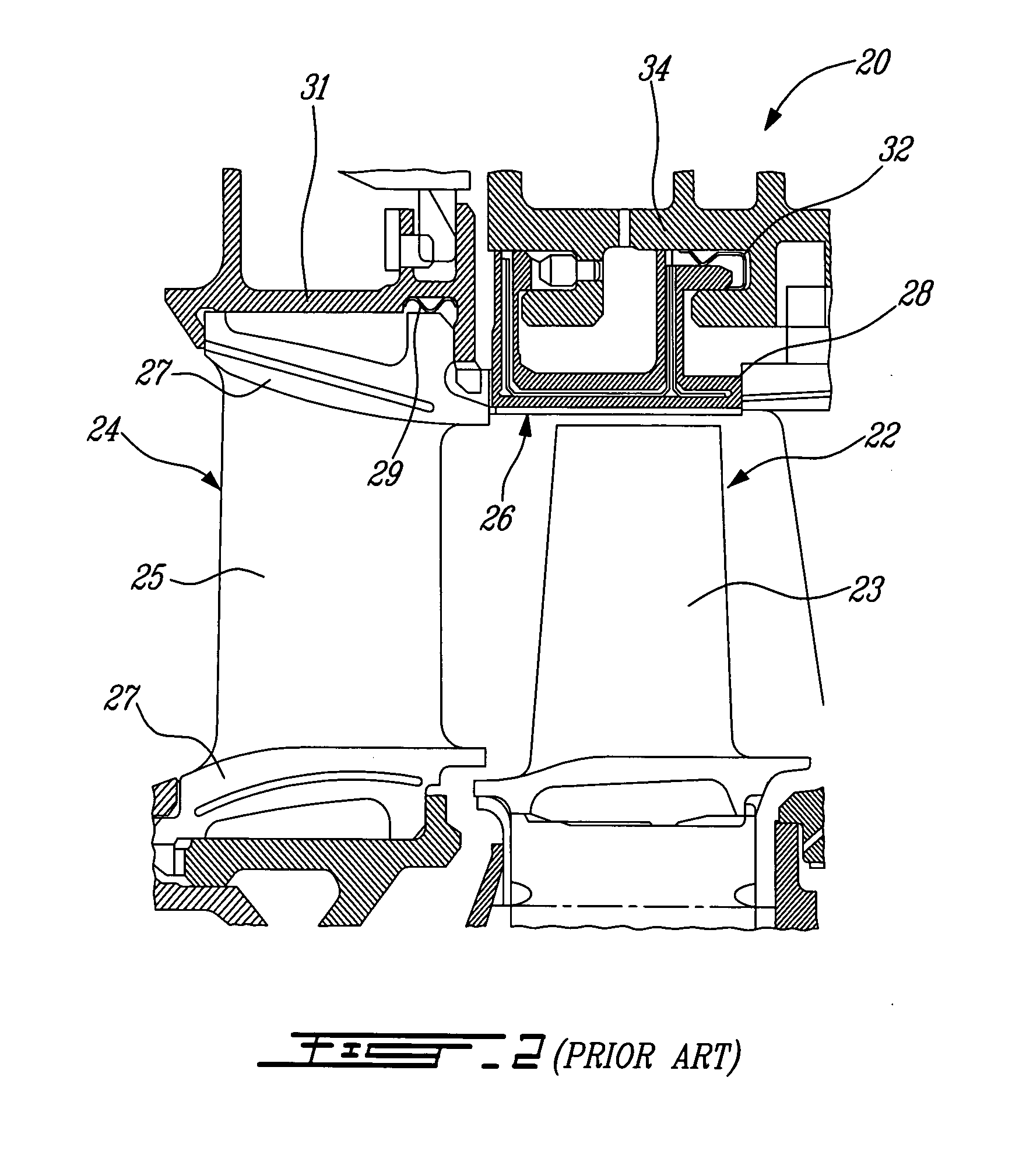
[0018] Referring to prior art FIG. 2, a turbine stage 20 of a gas turbine engine includes generally a turbine rotor 22 having a plurality of radially extending blades 23 and a turbine stator vane assemb...


PUM


Abstract

A ring seal for sealing an annular gap defined between opposed surfaces of concentric inner and outer annular engine parts in a gas turbine engine. The ring seal being wholly disposed within the annular gap and having a wave pattern with alternating peaks. The ring seal radially inwardly loads the inner engine part and provides a fluid seal between the inner and outer engine parts.

Description

TECHNICAL FIELD [0001] The invention relates generally to a seal for a gas turbine engine, and more particularly, to an improved turbine shroud segment seal. BACKGROUND OF THE ART [0002] Seals provided between turbine shroud segments and outer supporting housings in gas turbine engines are well-known. Such seals reduce gas flow between inner cooling air cavities, defined within the turbine shroud segments, and the main engine hot gas path defined radially within the turbine shroud segments. In many engine designs, relatively cool secondary air flow is fed from the compressor to the cooling cavities defined within the turbine shroud segments to provide cooling thereof. In order to prevent leakage of this cooling air into the main gas path, seals are preferably provided between the upstream and downstream edges of the turbine shroud segments and the outer supporting shroud housing. [0003] In order to achieve a tight clearance gap between the turbine blade tips and the surrounding shro...

Claims


Application Information

Patent Timeline
Patent Type & Authority Applications(United States)
IPC IPC(8): F01D11/08
CPCF01D11/08F01D25/12F02C7/12F02C7/28F05D2230/60F05D2230/10
Inventor SYNNOTT, REMYBLAIS, DANY
Owner PRATT & WHITNEY CANADA CORP
Why Eureka
Try Eureka