Method of controlling sharing of radio resources in mobile communication system

a mobile communication system and radio resource technology, applied in the direction of network traffic/resource management, electrical equipment, selection arrangements, etc., can solve the problems of large facility investment, difficult to implement optimal installation, and large radio resource consumption, so as to uniformly distribute radio resources, and avoid congestion of radio resources

Inactive Publication Date: 2006-04-20
FUJITSU LTD
View PDF14 Cites 36 Cited by
  • Summary
  • Abstract
  • Description
  • Claims
  • Application Information

AI Technical Summary

Benefits of technology

[0024] According to the second or the third aspect, it is possible to detect congestions of radio resources due to fixed factors, such as a concentration of mobile devices, in an event site or the like. It is also possible to obtain move record information of mobile devices or radio field intensity received by each mobile device. In both cases, by utilizing the move record information of mobile devices or the radio field intensity received by each mobile device detected in advance, radio base stations to which the mobile devices can be shifted are determined, when congestion occurs in the radio resources. Based on this decision, the mobile devices in the congested radio base stations are handed over to other non-congested radio base stations. As a result, it becomes possible to avoid congestions of radio resources due to fixed factors, such as a concentration of mobile devices, in an event site or the like. Further, by uniformly distributing the radio resources to peripheral radio base stations, the radio resources in the radio access network (RAN) can be effectively utilized.
[0025] According to a fourth aspect of the present invention, in controlling the distribution of radio resources corresponding to characteristics of mobile devices, when quality-of-service information (QoS) band-guaranteed mobile devices are present, the QoS band-guaranteed mobile devices can share idle resources that are not actually used by other band-guaranteed mobile devices, thereby uniformly sharing the radio resources. As a result, it becomes possible to uniformly distribute the radio resources more effectively.
[0026] It is necessary to guarantee bands to QoS band-guaranteed mobile devices even when these mobile devices are not actually using resources. Therefore, radio resources of guaranteed bands are always secured. However, along with the trend of band expansion in future, there is a risk of congestion in radio base stations due to the securing of bands at all times regardless of presence of radio resources that are not actually used. According to the present invention, mobile devices having the same characteristics of mobile devices can share the unused bands. Therefore, congestion in radio base stations due to presence of a large number of unused radio resources can be avoided.
[0027] According to a fifth aspect of the present invention, move characteristics of mobile devices are detected and are grouped in advance. With this arrangement, it becomes possible to forecast a mass handover when the mobile devices move in trains or buses. It is possible to forecast a shortage in radio resources at a move destination following the mass handover. When a shortage of resources in the destination radio base station is detected, radio base stations to which mobile devices are to be handed over, other than the destination radio base station, are determined based on the characteristics of mobile devices so that the radio resources can be used uniformly. By sequentially handing over the mobile devices to the radio base stations at the handover destinations, congestion in the destination radio base station due to the mass handover can be avoided. Further, the radio resources in the peripheral radio base stations can be distributed uniformly. As a result, radio resources in the radio access network (RAN) can be effectively utilized.

Problems solved by technology

The depletion of radio resources is a significant problem in a current mobile communication network as well, and efficient utilization of radio resources is required.
Therefore, it is difficult to implement an optimum installation, of machines, that takes congestion into account.
This requires an enormous amount of facility investment, and cannot be a realistic method of solving the problems from the viewpoint of cost.
This has a risk of rapid depletion of radio resources in the radio base stations at the handover locations.
In event sites and stations where people come together, there is also a similar risk of rapid depletion of radio resources that radio stations in the corresponding areas have.
This brings about a phenomenon that data communications cannot be carried out.
Therefore, the problem cannot be solved by simply increasing facility investment, and techniques for efficiently using radio resources are necessary.
These conventional techniques, however, have the following problems.
In this case, sudden congestion occurs in the radio base station at the handover location, and radio resources cannot be secured for these users.
It is also difficult to avoid total congestion in the radio access network (RAN).
However, the method of managing radio resources, classified by quality of service class (QoS), to guarantee a band for each user has the following problems.
(1) When the transmission bands are separately provided as individual transmission bands and a shared transmission band, the QoS band guarantee cannot be achieved in some cases.
However, despite the fact that bands are guaranteed to these users when the individual bands are in shortage, the users cannot be shifted to the individual bands, and the bands cannot be guaranteed.
(2) It is impossible to avoid congestion of the radio resources in the radio base station itself.
Therefore, when congestion occurs in the radio resources of the radio base station, this congestion cannot be avoided even if the transmission bands are switch-controlled.
However, because the total necessary number of radio resources in the base station does not change, this does not lead to the effective utilization of the radio resources.

Method used


Image

  • Method of controlling sharing of radio resources in mobile communication system
  • Method of controlling sharing of radio resources in mobile communication system
  • Method of controlling sharing of radio resources in mobile communication system

Examples


first embodiment

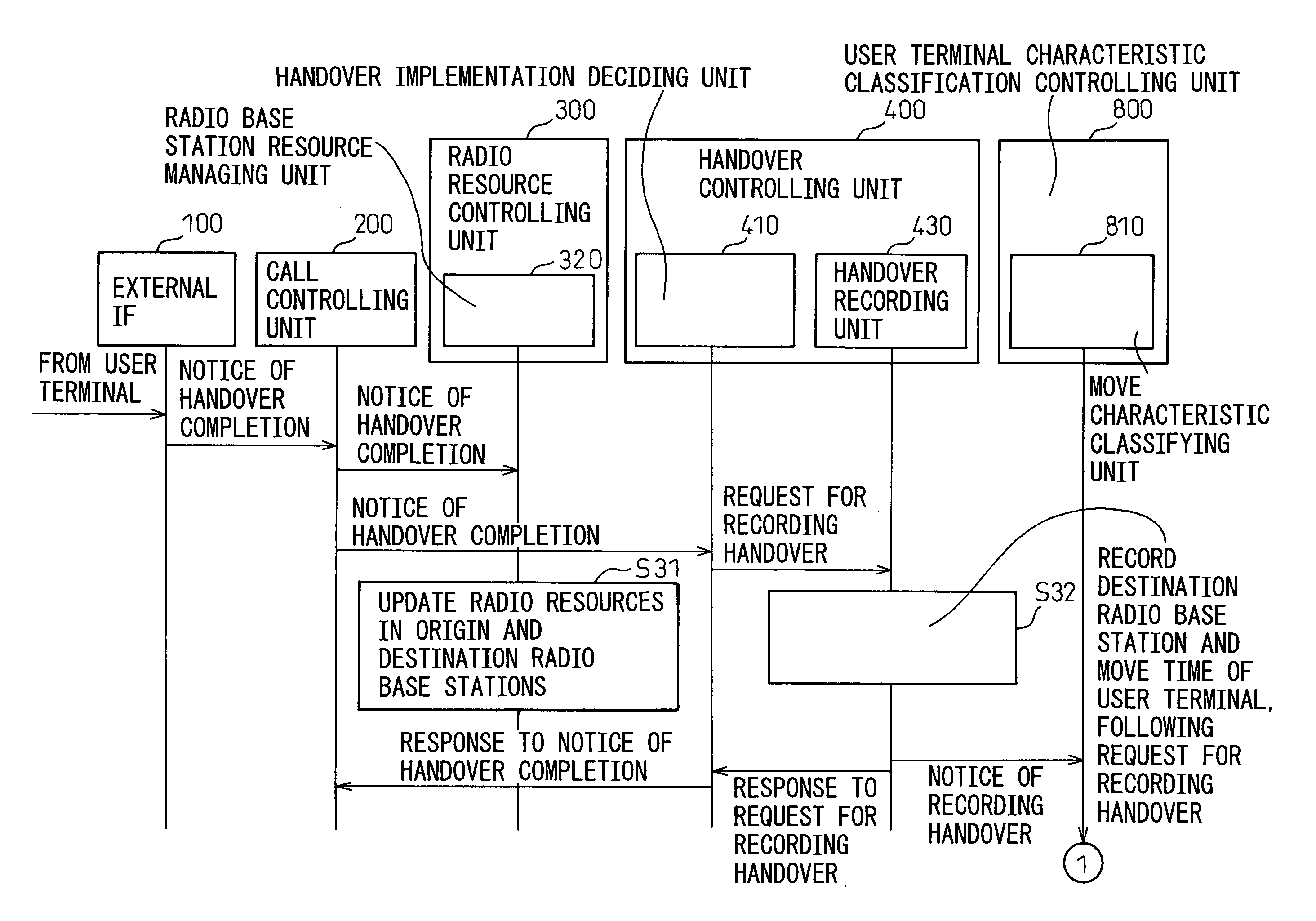
[0100]FIG. 3 and FIG. 4 are sequence diagrams of the operation of the move characteristic classifying unit 810 within the RNC shown in FIG. 2 according to a first embodiment (corresponding to claim 2) of the present invention.

[0101] Referring to FIG. 3 when the external IF 100 completes a handover following a handover request from a user terminal UE, the external IF 100 transmits a handover completion notice to the call controller 200. The call controller 200 transmits a handover completion notice containing an identification number of the user terminal UE and destination radio base station information, to both the radio resource controller 300 and the handover controller 400.

[0102] The radio resource controller 300 sends the handover completion notice to the radio base station resource managing unit 320 in order to update radio resources used in each radio base station. The radio base station resource managing unit 320 receives this handover completion notice, and subtracts radio...

second embodiment

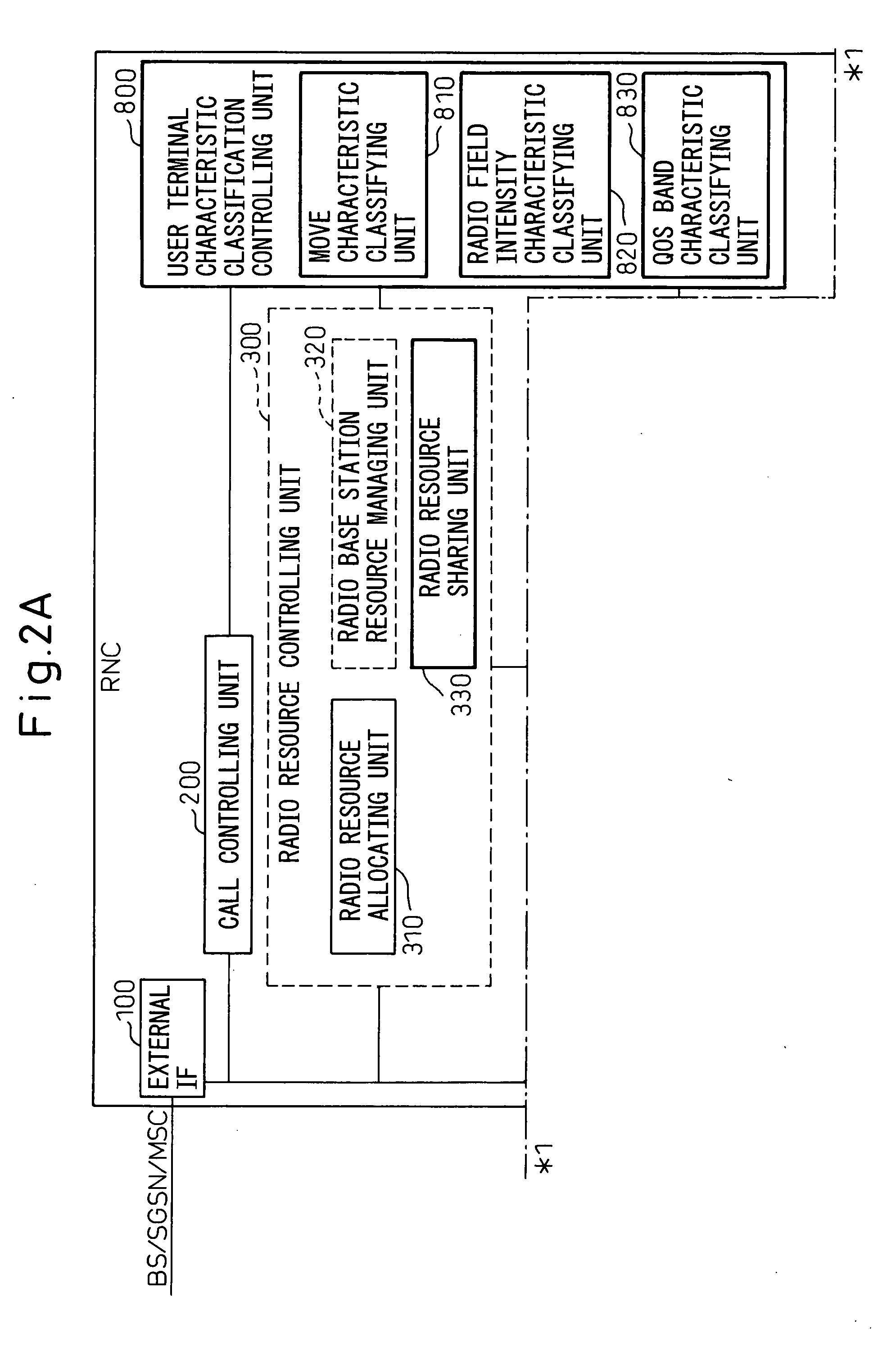
[0107]FIG. 5 is a sequence diagram of the operation of the radio field intensity characteristic classifying unit 820 within the RNC shown in FIG. 2 according to a second embodiment (corresponding to claim 3) of the present invention. Referring to FIG. 5, the external IF 100 receives a radio field intensity report from a user terminal UE, and transmits the radio field intensity report to the radio quality manager 700. At step S51, the radio quality manager 700 records the radio field intensity in the user terminal into the radio quality management database 710 based on a user terminal identification number and the radio field intensity in peripheral cells from the user terminal.

[0108] The radio quality manager 700 receives the radio field intensity report, and transmits the radio field intensity report to the user terminal characteristic classification controller 800, by using the user terminal identification number as additional information, in order to detect data classified accor...

third embodiment

[0110]FIG. 6 is a sequence diagram of the QoS band characteristic classifying unit 830 within the RNC shown in FIG. 2 according to a third embodiment (corresponding to claim 4) of the present invention. Referring to FIG. 6, the external IF 100 receives a call setting request from the SGSN or the MSC at the core network CN side, and transmits this call setting request to the call controller 200. The call controller 200 transmits a call information notice to the user terminal characteristic classification controller 800, the call information notice containing extracted information of a user terminal such as a user terminal identification number, QoS information, and a request band.

[0111] The user terminal characteristic classification controller 800 receives the call information notice, transmits a request for classifying data according to the QoS band characteristics, to the QoS band characteristic classifying unit 830, and prepares data classified according to the QoS band characte...


PUM


Abstract

A radio network controller in a mobile communication network detects characteristics of mobile devices that are wireless connected to a radio base station managed by the radio network controller. The radio network controller decides whether the mobile devices can be classified into at least one group according to the detected characteristics. When it is decided that the mobile devices can be classified into at least one group, radio base stations to which the mobile devices can be wireless connected are changed according to the classified group so that radio resources in the radio base stations can be uniformly used. By sharing the radio resources owned by a radio base station, the radio resources under the control of the radio network controller can be effectively utilized.

Description

CROSS-REFERENCE TO RELATED APPLICATIONS [0001] This application is based upon and claims the priority of Japanese Patent Application No. 2004-301452, filed on Oct. 15, 2004, the contents being incorporated herein by reference. BACKGROUND OF THE INVENTION [0002] 1) Field of the Invention [0003] The present invention relates to a method of controlling the sharing of radio resources to effectively utilize radio resources under control of a radio network controller (RNC) in a radio access network (RAN) based on a wideband code division multiple access (W-CDMA). [0004] 2) Description of the Related Art [0005] Along with the rapid distribution of portable telephones in recent years, portable telephones are widely used to handle various multimedia services such as sound, moving images, and data communications. Among others, the role of data communications is increasing. The W-CDMA system is a standardized system to provide high-quality multimedia services at a high speed. Recently, the app...

Claims


Application Information

Patent Timeline
Patent Type & Authority Applications(United States)
IPC IPC(8): H04Q7/20H04W28/08H04W28/26
CPCH04W28/08H04W28/26H04W72/52
Inventor MINAMI, SHINJIOISHI, YUICHIROSEGUCHI, YOSHIYUKI
Owner FUJITSU LTD
Why Eureka
Try Eureka