Spindle motor and disk drive device

a spindle motor and disk drive technology, applied in the direction of dynamo-electric components, instruments, data recording, etc., can solve the problems of rotor eccentricity in a certain direction, extremely troublesome assembly, and unbalance of magnetic field, so as to prevent oil scattering, improve axial run-out qualities, and prevent oil scattering

Inactive Publication Date: 2006-04-20
TOKYO PARTS IND CO LTD
View PDF14 Cites 8 Cited by
  • Summary
  • Abstract
  • Description
  • Claims
  • Application Information

AI Technical Summary

Benefits of technology

[0018] According to the present invention, with a simple constitution of an annular magnet and annular magnetic material opposite the annular magnet, scattering of oil can be prevented and a rotor can be reliably eccentric and ca

Problems solved by technology

In such a constitution a prescribed section of a magnetic plate shaped stator core comprising a plurality of stacked magnetic plates is cut away, thereby creating magnetic unbalance with respect to a drive magnet provided on a rotor, thus causing the rotor to be eccentric in a

Method used


Image

  • Spindle motor and disk drive device
  • Spindle motor and disk drive device
  • Spindle motor and disk drive device

Examples


Embodiment Construction

:

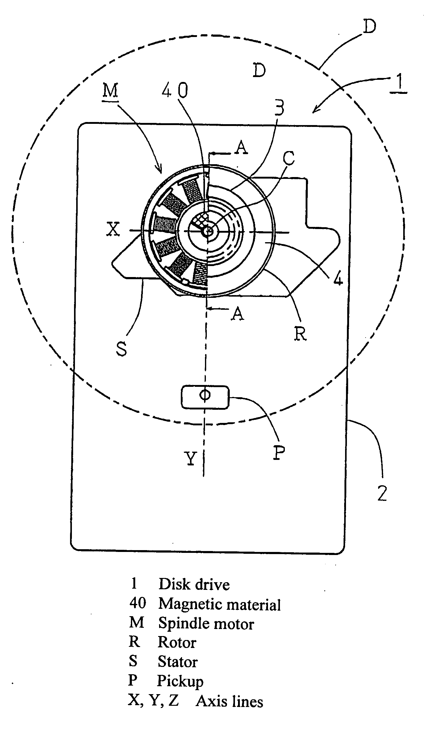
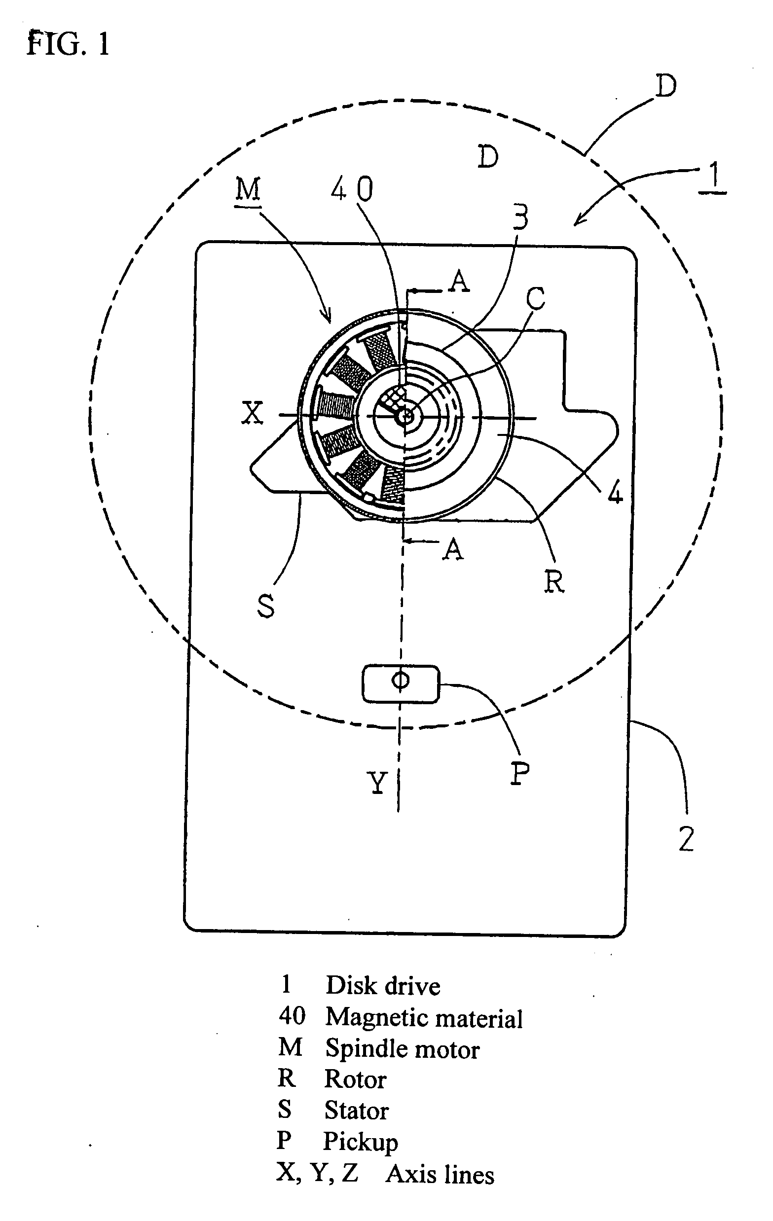
[0019] A disk drive according to the present invention will be explained with reference to FIG. 1. FIG. 1 illustrates a plan view showing a disk drive, with a cross-sectional view of half the rotor along the line AA.

[0020] A disk drive 1 comprises, on a chassis 2, a spindle motor M and a pickup P that serves as a read head. The pickup P is attached on the chassis 2 so that the optical axis of a laser beam passes through a rotation center C and moves along an axis line Y (first axis line) parallel to the rotary surface of the disk. Explanations of a mechanism to move a pickup, signal processing, a motor drive circuit and the like are omitted, as they do not directly relate to the present invention.

[0021] Here, to simplify the explanation, we will designate as line X (second axis line) a line passing through the rotation center C and parallel to the disk rotary surface, and intersecting with the axis line Y at a right angle. Further, we will designate as line Z an axis line (axis l...


PUM


Abstract

Problem:
With a simple constitution, to cause a spindle motor rotor to be eccentric in a pickup moving direction and to improve axial run-out caused by clearance between a rotating shaft and bearing.
Means for Solving the Problems:
A magnetic cap 40 is attached to an end 7e of a bearing 7 of a spindle motor M so as to cover an end face 7f. A ceiling 41 of the magnetic cap 40 is an annular magnetic material in which a lid 40g and opposing face 40a protruding therefrom are continuous, and the opposing face 40a works with an annular magnet 13 attached to the rotor to generate an attraction force F that causes the rotor R to be eccentric. The opposing face 40a is formed so as to be linearly symmetrical with respect to the axis line Y, which is the pickup movement line.

Description

TECHNICAL FIELD [0001] The present invention relates to a spindle motor for rotatably driving an optical disk, magneto-optical disk or the like, and a disk drive comprising the spindle motor and an optical read head for reading information recorded on the disk. Background Art [0002] A disk drive comprising a read head for optically reading information recorded on a disk is known as an optical disk / magneto-optical disk drives such as CD, DVD, and MD. [0003] In such a disk drive, an outer rotor type brushless motor is employed as a so-called spindle motor for rotatably driving a disk. A turntable on which a disk is placed is provided on a rotating shaft of the spindle motor so as to rotate integrally therewith, and the rotating shaft is rotatably supported by a bearing on the stator. [0004] A sintered oil-impregnated metal bearing is used; this is because such a bearing is less expensive than a roller bearing and thus can reduce the costs of a motor and device. However, unlike a rolle...

Claims


Application Information

Patent Timeline
IPC IPC(8): G11B19/20G11B17/028G11B17/03
CPCG11B19/2009
Inventor NISHIDATE, MASAHIRO
Owner TOKYO PARTS IND CO LTD
Why Eureka
Try Eureka