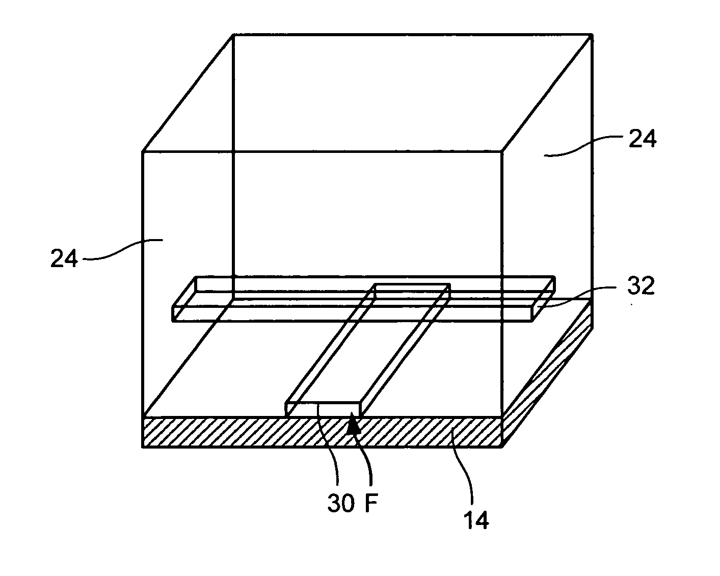
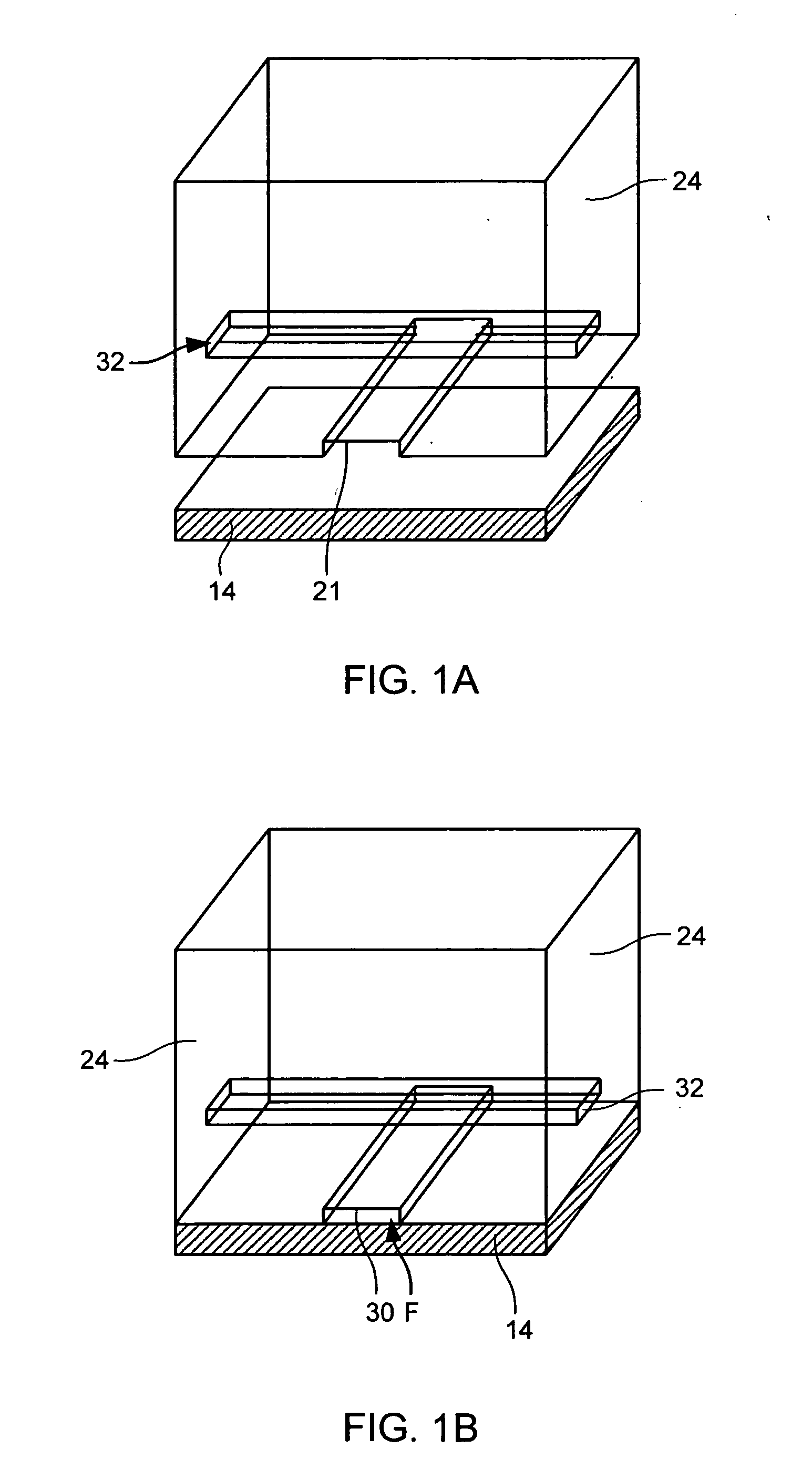
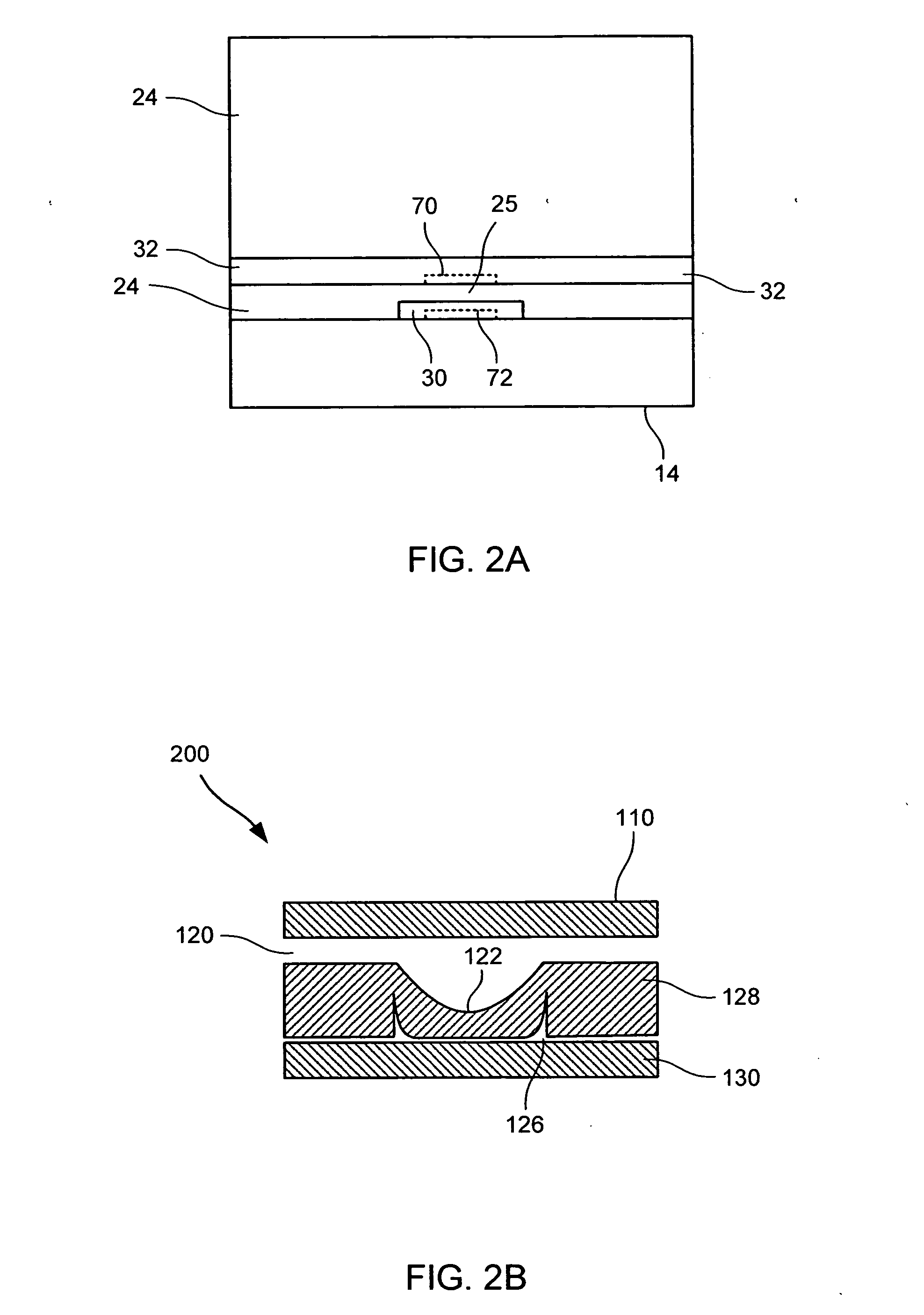
Recirculating fluidic network and methods for using the same

a fluid network and fluid technology, applied in the field of microfluidic devices, can solve the problems of limiting the usefulness of current microfluidic devices, requiring only a minimal amount of samples, and requiring only a small amount of samples

Inactive Publication Date: 2006-04-27
FLUIDIGM CORP
View PDF99 Cites 48 Cited by
  • Summary
  • Abstract
  • Description
  • Claims
  • Application Information

AI Technical Summary

Problems solved by technology

Assays preferably require a minimal amount of assay components in order to minimize costs; this becomes a particular issue if certain assay components are expensive and / or a large number of assays are to be conducted.
Ideally, assays require only a minimal amount of sample because often only a very limited amount of sample is available.
Unfortunately, current microfluidic devices suffer from a number of shortcomings that limit their usefulness.
Such chips, however, are brittle and the stiffness of the material often necessitates high actuation forces.
The stiffness of the devices also imposes significant constraints on options for controlling solution flow through the microchannels.
Reliance on electrodes, however, creates several problems.
One problem is that gas is often generated at the electrodes.
This can increase pressure within the device potentially causing separation of microfabricated layers.
The increased pressure and gas bubbles can also interfere with solution flow through the channels.
Fabrication of such a network can be complicated and increases the expense of the devices.
The need for such networks also becomes particularly problematic if a device is to be prepared that includes a large number of channels to facilitate multiplexed and high throughput assay capabilities.
In addition, the use of electric fields can be problematic for applications involving cells as application of the electric fields can negatively affect the cells, often killing them.

Method used


Image

  • Recirculating fluidic network and methods for using the same
  • Recirculating fluidic network and methods for using the same
  • Recirculating fluidic network and methods for using the same

Examples


example 1

[0197] This example illustrates a method for producing a 4-layer microfluidic device having protein A (Staphylococcus aureus Fc binding protein) on its surface. The 4-layer device enables an assay to be performed at a precise location on a given solid substrate.

[0198] A fluid flow channel mold was prepared by spinning Shipley 5740 at 3600 rpm for 30 sec, soft baking for 60 s at 105° C. (measured thickness=7.8 μm), and hardbaking at 140° C. for 150 sec. (final mold thickness=10 μm). A control channel mold was prepared by spinning shipley 5740 at 850 rpm for 30 sec, followed by 5 min rest period prior to soft baking for 180 sec at 105° C. (final mold thickness=20 μm). A via mold was prepared by spinning AZ PLP 100-XT at 1240 rpm for 30 sec. followed by soft baking for 8 min at 95° C. (final mold thickness=35 μm).

[0199] Exemplary mold designs for each of the corresponding control layer (808), the fluid (i.e., flow channel) layer (804), and the via layer (812) are shown in FIGS. 8A-E....

example 2

[0237] This example illustrates a method for using a microfluidic device of the present invention for conducting a FLISA assay.

[0238] Using a microfluidic device of configuration shown in FIG. 11, various assays were conducted as follows:

Fluid Inputs

[0239] Fluid inputs A, B, C, and D are the reagent inlets. Through these inlets solutions of reagents, such as an antibody, can be added. When the proper valves are actuated, fluid flow from these inputs are directed into discrete areas of the chip. Fluid inputs E, F, G, and H are the sample inlets. Through these inlets solutions of reagents, such as analytes or antigens, can be added. When the proper valves are actuated, fluid flow from these inputs are directed into discrete areas of the chip. Fluid input I is a common wash inlet. This input connects to fluid lines adjacent to fluid inputs E-H. It may contain buffers or solutions common to all samples. It can also contain a buffers or solution to block the channel walls or block th...


PUM

PropertyMeasurementUnit
Tmaaaaaaaaaa
melting temperatureaaaaaaaaaa

Abstract

The present invention provides microfluidic devices and methods for using the same. In particular, microfluidic devices of the present invention are useful in conducting a variety of assays and high throughput screening. Microfluidic devices of the present invention include elastomeric components and solid substrate component for attaching ligand(s) on its surface. The elastomeric layer comprises (a) a plurality of first flow channels; (b) a plurality of second flow channels each intersecting and crossing each of said first flow channels thereby providing a plurality of intersecting areas formed at intersections between said first flow channels and said second flow channels, wherein said plurality of first flow channels and said plurality of second flow channels are adapted to allow the flow of a solution therethrough, and wherein said solid substrate surface is in fluid communication with at least said intersecting areas of said plurality of first flow channels and said plurality of second flow channels, and wherein said plurality of first flow channels and / or said plurality of second flow channels are capable of forming a plurality of looped flow channels; (c) a plurality of control channels; (d) a plurality of first control valves each operatively disposed with respect to each of said first flow channel to regulate flow of the solution through said first flow channels, wherein each of said first control valves comprises a first control channel and an elastomeric segment that is deflectable into or retractable from said first flow channel upon which said first control valve operates in response to an actuation force applied to said first control channel, the elastomeric segment when positioned in said first flow channel restricting solution flow therethrough; (e) a plurality of second control valves each operatively disposed with respect to each of said second flow channel to regulate flow of the solution through said second flow channels, wherein each of said second control valves comprises a second control channel and an elastomeric segment that is deflectable into or retractable from said second flow channel upon which said second control valve operates in response to an actuation force applied to said second control channel, the elastomeric segment when positioned in said second flow channel restricting solution flow therethrough; (f) a plurality of loop forming control valves each operatively disposed with respect to each of said first and / or said second flow channels to form said plurality of looped flow channels, wherein each of said loop forming control valves comprises a loop forming control channel and an elastomeric segment that is deflectable into or retractable from said first and / or said second flow channels upon which said loop forming control valve operates in response to an actuation force applied to said loop forming control channel, the elastomeric segment when positioned in said first and / or said second flow channels restricting solution flow therethrough thereby forming said looped flow channel; and (g) a plurality of recirculating pumps, and wherein each recirculating pump is operatively disposed with respect to one of said looped flow channels such that circulation of solution through each of said looped flow channels can be regulated by one of said recirculating pumps.

Description

CROSS-REFERENCES TO RELATED APPLICATIONS [0001] This application claims the benefit of U.S. Provisional No. 60 / 391,292, filed Jun. 24, 2002, which is incorporated herein by reference in its entirety for all purposes.FIELD OF THE INVENTION [0002] The present invention relates to microfluidic apparatus and methods for using the same, such as conducting a variety of assays. BACKGROUND OF THE INVENTION [0003] There are several goals in the development of biological assays, including utilization of a minimal amount of assay components and sample, simplicity in operation and high throughput capability. Assays preferably require a minimal amount of assay components in order to minimize costs; this becomes a particular issue if certain assay components are expensive and / or a large number of assays are to be conducted. Ideally, assays require only a minimal amount of sample because often only a very limited amount of sample is available. The goal of simplicity of operation often means that t...

Claims


Application Information

Patent Timeline
Patent Type & Authority Applications(United States)
IPC IPC(8): H01L21/322B01L3/00B81CF04B19/00F04B43/02G01N21/00G01N33/53G01N33/543G01N33/566G01N37/00
CPCB01L3/5025Y10T436/2575B01L3/50273B01L3/502738B01L2300/0636B01L2300/0645B01L2300/0816B01L2300/0861B01L2300/088B01L2300/0887B01L2400/0415B01L2400/0481B01L2400/0655F04B19/006F04B43/02F16K99/0001F16K99/0003F16K99/0026F16K99/0036F16K99/0046F16K99/0051F16K99/0059F16K2099/0074F16K2099/0078F16K2099/008F16K2099/0084G01N33/54366B81B3/00B01L3/502707F04B43/14G01N33/5304
Inventor MANGER, IANDBARCO, JOSEPHWNASSEF, HANYR
Owner FLUIDIGM CORP
Why Eureka
Try Eureka