Pneumatic tire

Active Publication Date: 2006-04-27
SUMITOMO RUBBER IND LTD
View PDF9 Cites 15 Cited by
  • Summary
  • Abstract
  • Description
  • Claims
  • Application Information

AI Technical Summary

Benefits of technology

[0007] That is, the present invention relates to an improvement of a sipeing of the MIURA-ori structure, and it is an object of the invention to provide a pneumatic tire capable of more smoothly pulling the knife blade from the tire while highly securing the suppressing effect on falling of the block. It is another object of the invention to provide a pneumatic tire capable of further enhancing the producing efficiency of the tire and enhancing the suppressing effect of bending and damage of the knife blade.
[0020] According to the sipeing of the MIURA-ori structure of the present invention, the knife blade can be pulled out from the tire more smoothly while highly securing the fall-preventing effect of the block, the producing efficiency of the tire can be enhanced, and bending and damage suppressing effect on the knife blade can further be enhanced.

Problems solved by technology

If the number of sipeings is increased, however, the degree of falling down of becomes large.
As a result, if the edge effect does not function effectively, and the running performance on the ice road is deteriorated.

Method used


Image

  • Pneumatic tire
  • Pneumatic tire
  • Pneumatic tire

Examples


examples

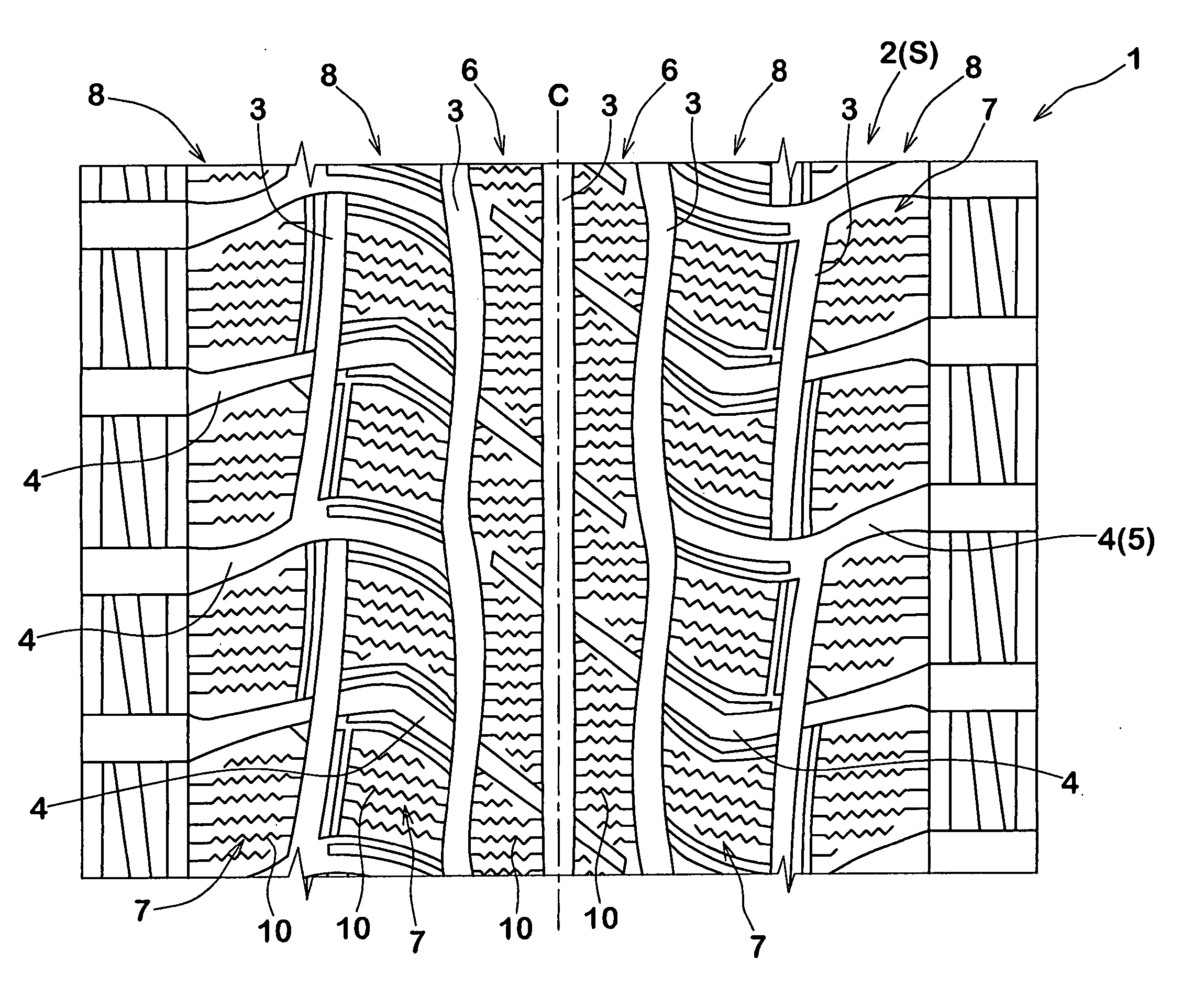
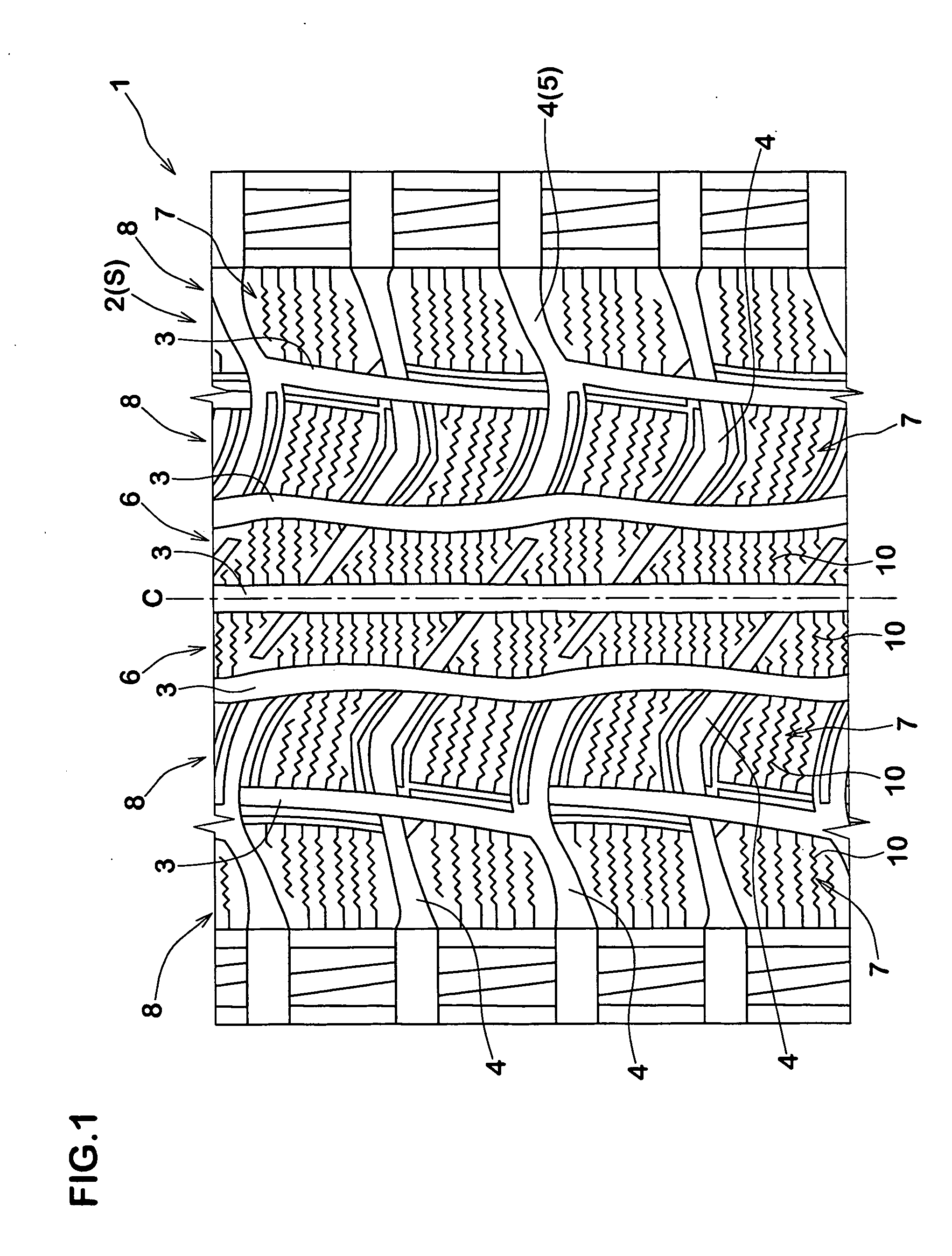
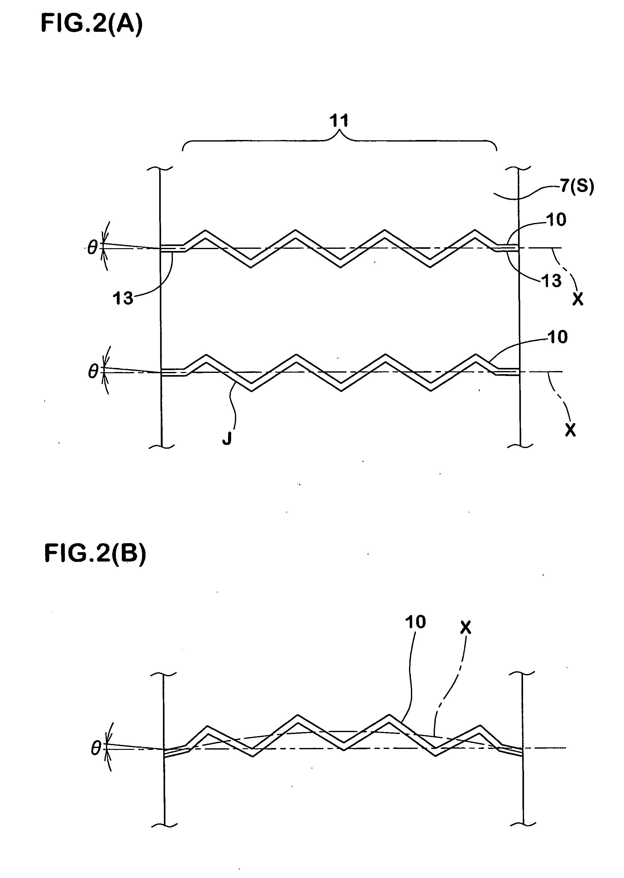
[0056] Studless tires (size 195 / 65R15) for a passenger vehicle having block pattern comprising four block lines using a rectangular block were produced based on specification shown in Table 1. Block rigidities of the blocks and pulling-out resistance of the knife blade were measured. The rectangular block has size of 15 mm (width in axial direction of the tire)×20 mm (length in circumferential direction of the tire)×10 mm (height). Four 3D sipeings having 0.3 mm (sipeing width)×9.0 mm (sipeing depth) are formed in each block surface at equal distances from one another. The opening edge shapes on the block surface are the same in all tires, and the zigzag amplitude of the zigzag shape is 1.3 mm, and zigzag pitch is 3.6 mm.

[0057] (1) Block rigidity;

[0058] Normal internal pressure was charged into the prototyped tire, vertical load of 0.0274 kgf / mm2 was applied to the block surface, the road surface was displaced from 0 mm to 3.0 mm in the circumferential direction of the tire, and r...


PUM

PropertyMeasurementUnit
Fractionaaaaaaaaaa
Molar densityaaaaaaaaaa
Volumeaaaaaaaaaa

Abstract

It is possible to reduce pulling-out resistance of a knife blade from a tire while highly securing fall-preventing effect on block. A tread portion 2 has a block 7 provided with sipeings 10. The sipeing 10 has a zigzag portion 11 in an opening edge shape J at a block surface S, and zigzag displacement portions which are displaced toward one end of a longitudinal direction Fn and the other end are alternately repeated to form the zigzag portion 11 in a depth direction. When displacement amounts of a zigzag displacement portion 15U on the side of block surface, a zigzag displacement portion 15L on the side of sipeing bottom and an intermediate zigzag displacement portion 15M in a direction Fv perpendicular to the longitudinal direction Fn are defined as W1, W3 and W2, the following expressions are satisfied. W1≧W2 0.7×W2≧W3>0

Description

BACKGROUND OF THE INVENTION [0001] The present invention relates to a pneumatic tire which includes a plurality of sipeings provided side-by-side in a block, and which can be employed as a studless tire suitable for running on an ice and snow road surface. [0002] In the pneumatic tire, in order to enhance the running performance on an ice and snow road surface, a block provided in a tread portion is formed with a large number of sipeings. By increasing a road surface scratching force (edge effect) obtained by the edge of the sipeing, the driving force and braking force on the ice and snow road are secured. If the number of sipeings is increased, however, the degree of falling down of becomes large. As a result, if the edge effect does not function effectively, and the running performance on the ice road is deteriorated. [0003] Thereupon, to prevent the block from excessively fall, a zigzag type sipeing structure as shown in FIG. 9, is proposed in Japanese published patent applicatio...

Claims


Application Information

Patent Timeline
IPC IPC(8): B60C11/12B60C11/13
CPCB29D2030/0613B60C11/0306B60C11/12B60C11/1218B60C2011/1213Y10S152/03Y10S152/902
Inventor KISHIDA, MASAHIRO
Owner SUMITOMO RUBBER IND LTD
Why Eureka
Try Eureka