Correlation interferometer geolocation

a correlation interferometer and geolocation technology, applied in direction finders, direction finders using radio waves, instruments, etc., can solve the problems of affecting correct ambiguity resolution, affecting the accuracy of transmitter location, and difficult to achieve long baselines, etc., to achieve the effect of the same or greater transmitter location accuracy

Active Publication Date: 2006-04-27
BAE SYST INFORMATION & ELECTRONICS SYST INTERGRATION INC
View PDF7 Cites 42 Cited by
  • Summary
  • Abstract
  • Description
  • Claims
  • Application Information

AI Technical Summary

Benefits of technology

[0020] As will be appreciated, the number of antenna elements required by airborne DF interferometer systems leaves a limited amount of space for other sensors on the aircraft's exterior. Thus, it is desirable to provide a DF interferometer system for aircraft that needs only a few antenna elements while providing the same or greater transmitter location accuracy as prior art systems.

Problems solved by technology

Thus, the desire for accurate bearing measurements, requiring a long interferometer baseline, conflicts with the need for robust phase or AOA ambiguity resolution, which is easier to accomplish with a short baseline.
In addition, long baselines are difficult to achieve when the receiving apparatus is on an aircraft.
Additionally, vibration can distort the trend and hinder correct ambiguity resolution.
Observer attitude motion can cause large changes in the ambiguity integer, m. These changes are difficult to separate from translational motion relative to the emitter.
Another drawback to the phase tracking approach is that the number of lobes, i.e. potential solutions, is determined by the ratio of d / λ, where d is the baseline length and λ is the signal wavelength.
This approach has a limitation in that it cannot handle signals from arbitrarily polarized transmissions.
The use of the SBI phase difference to initially compute a slant range means this method will not initially converge faster than a more conventional SBI-only system until range accuracy sufficient to resolve the LBI has been achieved.
However, this SBI / LBI technique has the drawback of limiting the SBI / LBI baseline ratio, and requiring the use of a medium baseline interferometer (MBI) in many cases.
This introduces extra complexity, cost and weight to a system.
However, simply increasing DF aperture sizes without increasing the number of DF antennas leads to large amplitude correlation side lobes and a real potential for large errors.
Therefore, such prior art DF systems require many antennas and DF receivers and are very expensive.
The need for more antennas and more DF receivers negatively affects their use on aircraft.
As will be appreciated, the number of antenna elements required by airborne DF interferometer systems leaves a limited amount of space for other sensors on the aircraft's exterior.

Method used


Image

  • Correlation interferometer geolocation
  • Correlation interferometer geolocation
  • Correlation interferometer geolocation

Examples


Embodiment Construction

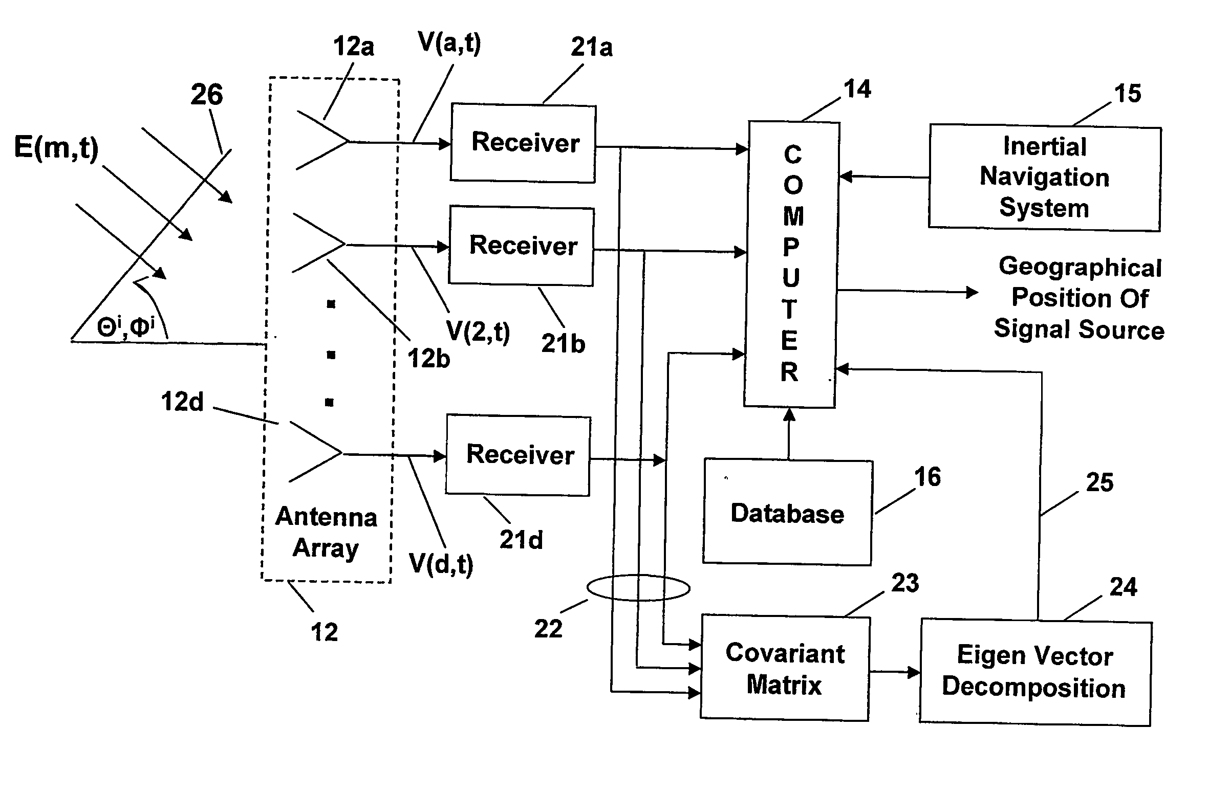
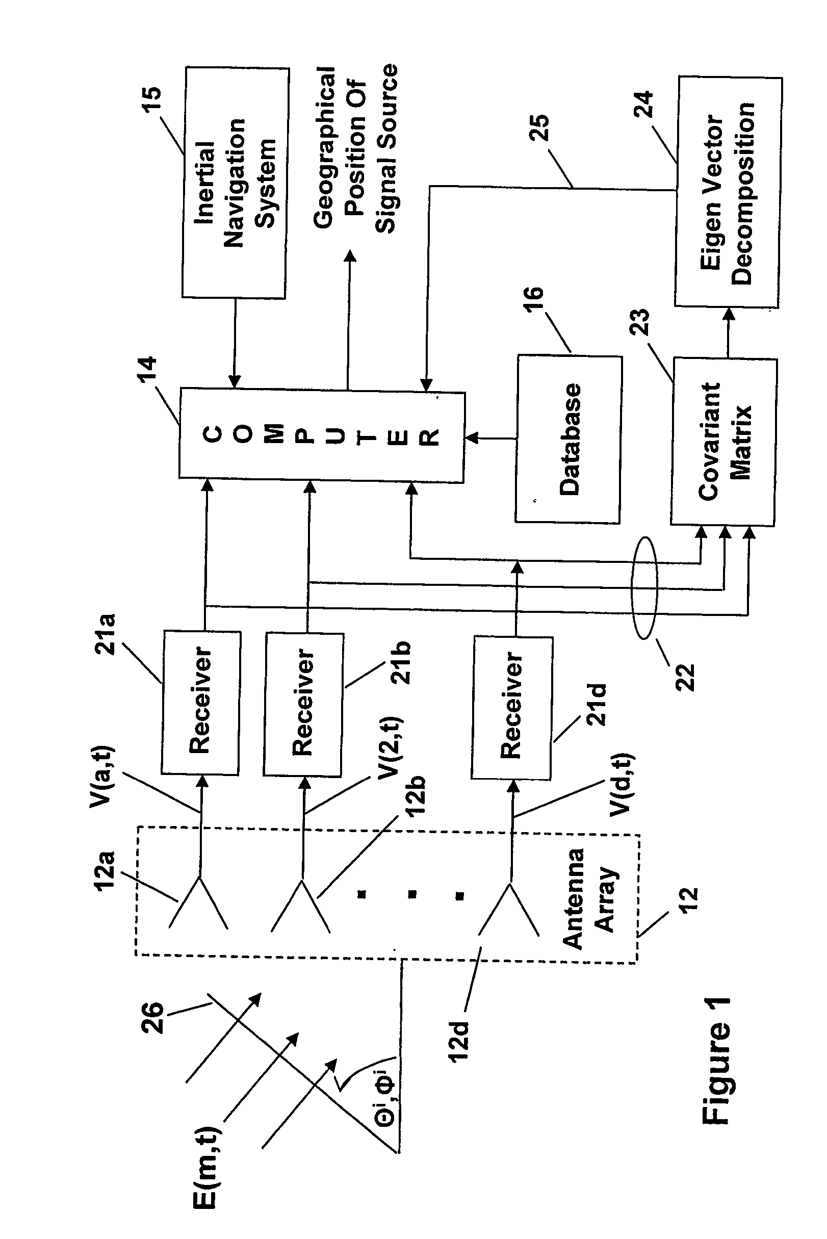
[0037] In the following detailed description and the drawings there are numerous terms used that are defined below:

Ap1(θ,φ) and Ap2(θ,φ)=orthogonal calibration array manifolds

Ar=antenna array response vector

AOA=angle of arrival

CIDF=Correlation interferometer direction finding

CIGL=correlation interferometer geo-location

DF=direction finding

E=electromagnetic radio waves incident on the array of antennas

LBI=long base line interferometer

LOB=lines of bearing

MBI=medium base line interferometer

Na=number of antennas in the beam forming / direction finding array

(O)*=complex conjugate of (O)

PI-CIGL=polarization independent correlation interferometer geo-location

Q=signal eigenvector of the measured covariance matrix

|R(xi,yj)|2=global correlation surface over a set of (xi,yj) grid points

Rxx=measured covariance matrix

SBI=short base line interferometer

SNR=signal-to-noise ratio

Vn(θ,φ) and Hn(θ,φ)=vertical and horizontal calibration array manifolds

V(n,t) antenna...


PUM


Abstract

Correlation Interferometer Geo Location (CIGL) uses DF antenna array movement on an aircraft while taking a Plurality of sets of transinitted signal Measurements. Each measurement set is stored as data in a covariance matrix, and the matrices are each decomposed to yield measured array vectors. Using an array manifold table developed during calibration of the CIGI. system, and containing testing array vectors, the measured array vectors are each correlated to testing array vectors to develop a correlation Surface that includes compensation for perturbations Such as aircraft induced electromagnetic scattering, All the correlation surfaces are summed and normalized, with the resultant summation undergoing conjugate gradient processing to more accurately geo-locate the transmitter. Improved accuracy with fewer antennas and polarization independence are also achieved.

Description

CROSS REFERENCE TO RELATED APPLICATION [0001] This utility patent application claims rights under 35 U.S.C. 119(e) from U.S. provisional patent application No. 60 / 456,299 entitled “Method For Correlation Geo-Location”, and filed Mar. 20, 2003.FIELD OF THE INVENTION [0002] The present invention relates to direction finding and, more particularly, to correlating signals received from a remote transmitter using an antenna array to determine the geographical location of the remote transmitter. BACKGROUND OF THE INVENTION [0003] In the earliest prior art the method of locating the position of a remote transmitter was to utilize a direction finding (DF) triangulation technique where signals from the transmitter are received at widely spaced DF antenna sites. A line-of-bearing (LOB) measurement to the transmitter is measured at each antenna site. When the LOBs are plotted on a map they intersect at the transmitter location. The accuracy of this intersection is directly related to the accur...

Claims


Application Information

Patent Timeline
Patent Type & Authority Applications(United States)
IPC IPC(8): G01S3/02G01S3/48H04B
CPCG01S3/46G01S5/04G01S5/12
Inventor STRUCKMAN, KEITH A.
Owner BAE SYST INFORMATION & ELECTRONICS SYST INTERGRATION INC
Why Eureka
Try Eureka