Method and apparatus for etch endpoint detection

a technology of endpoint detection and etching, applied in the field of endpoint detection, can solve the problems of false endpoint call, plasma optical emission is sensitive to changes in chamber conditions, and perturbation of plasma optical emission,

Active Publication Date: 2006-04-27
LAM RES CORP
View PDF6 Cites 155 Cited by
  • Summary
  • Abstract
  • Description
  • Claims
  • Application Information

AI Technical Summary

Benefits of technology

[0010] Broadly speaking, the present invention provides a method and an apparatus for monitoring a plasma optical emission. More specifically, the present invention provides a method for monitoring the plasma optical emission through a variable aperture to detect an endpoint of a plasma etching process without interferences that could lead to false endpoint calls. The method of the present invention requires the variable aperture to be maintained in a fixed position during a time period in which an endpoint occurrence is anticipated. Maintaining the aperture in the fixed position avoids perturbations in the observed plasma optical emission signal that could be misinterpreted as a false endpoint.

Problems solved by technology

One problem with current optical spectrometry endpoint detection methods is that the plasma optical emissions are sensitive to changes in the chamber conditions.
Thus, changes in the chamber conditions can introduce perturbations in the plasma optical emissions.
In some instances these perturbations in the plasma optical emissions can be comparable to an expected perturbation used to trigger an endpoint call, thus causing a false endpoint call to occur.

Method used


Image

  • Method and apparatus for etch endpoint detection
  • Method and apparatus for etch endpoint detection
  • Method and apparatus for etch endpoint detection

Examples


Embodiment Construction

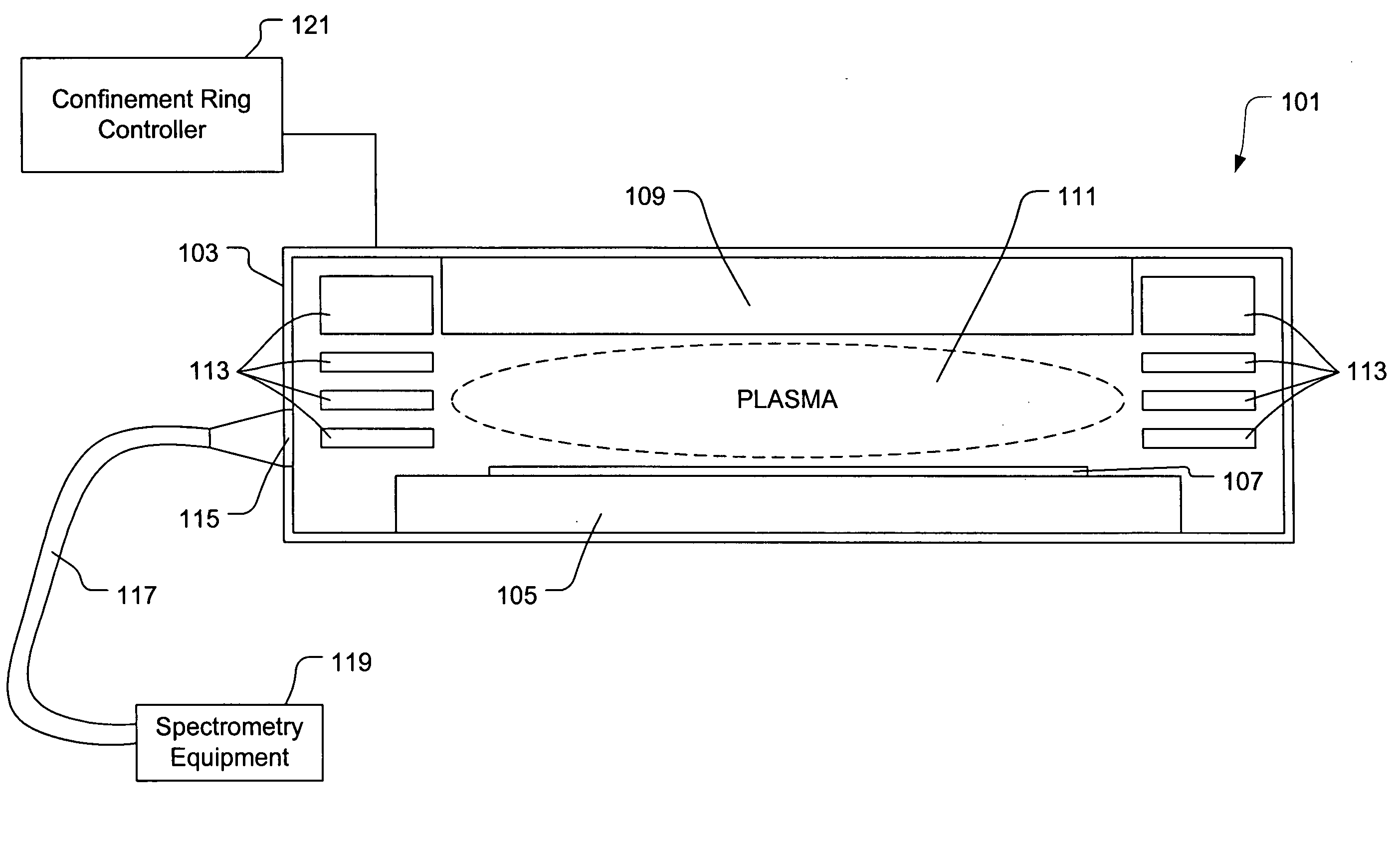
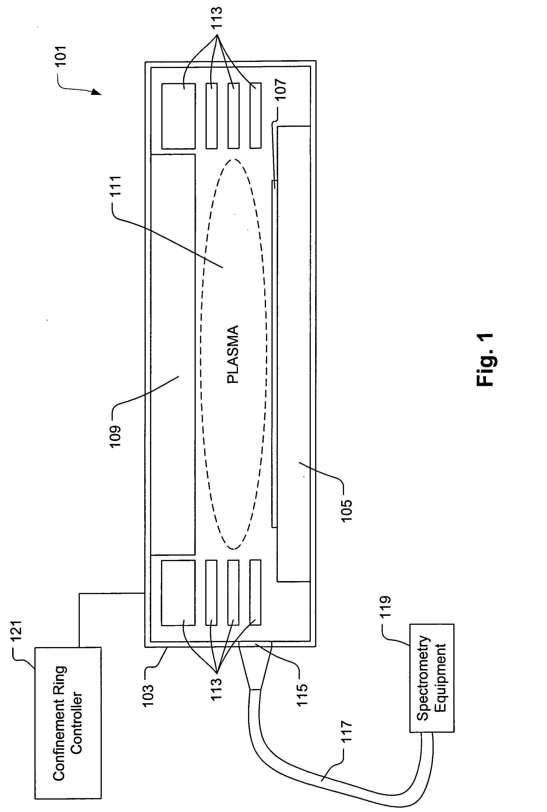
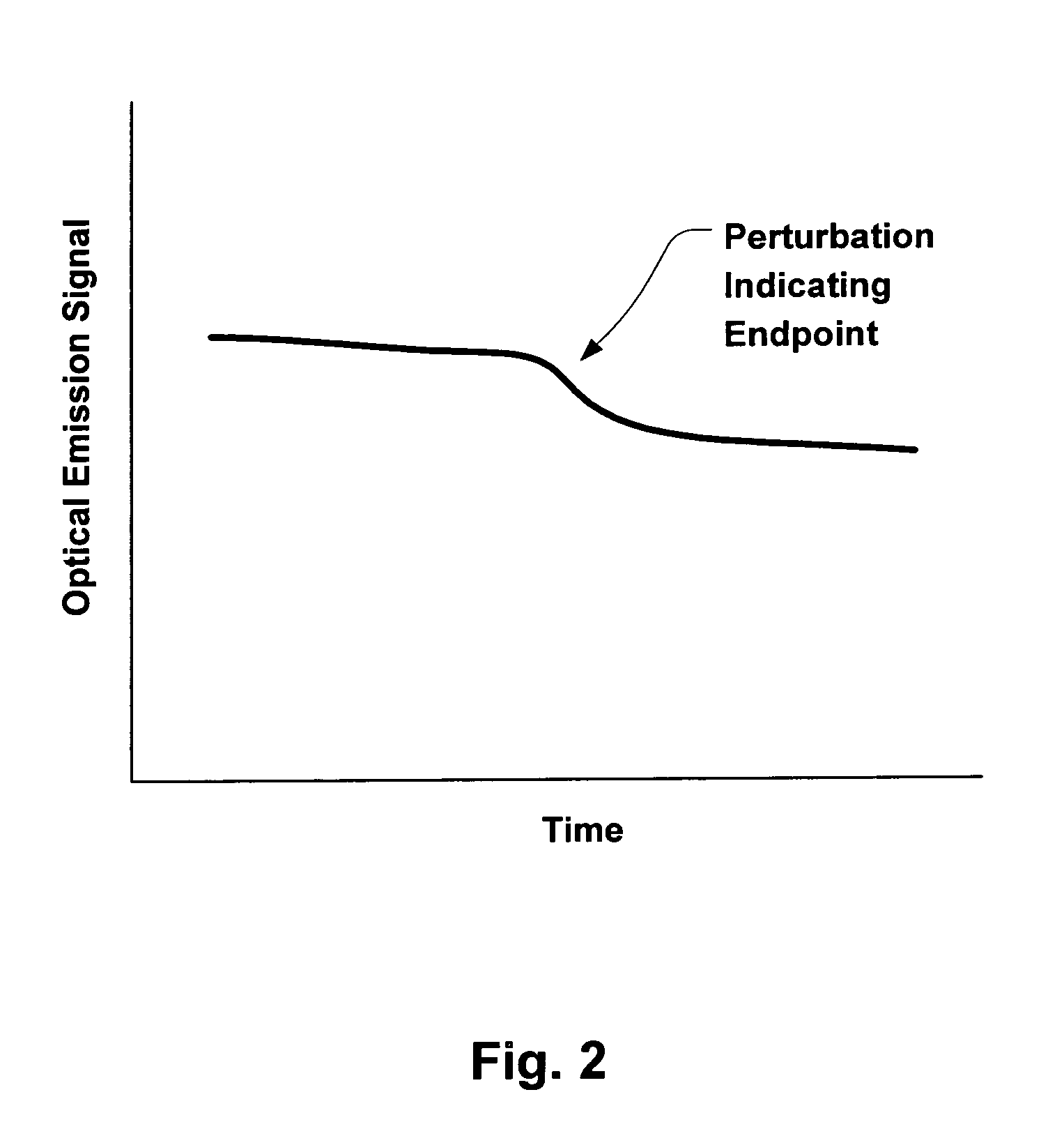
[0023] Broadly speaking, a method and an apparatus is provided for monitoring a plasma optical emission. More specifically, the present invention provides a method for monitoring the plasma optical emission through a variable aperture to detect an endpoint of a plasma etching process without interferences that could lead to false endpoint calls. The method of the present invention requires the variable aperture to be maintained in a fixed position during a time period in which endpoint occurrence is anticipated. Maintaining the aperture in the fixed position avoids perturbations in the observed plasma optical emission signal that could be misinterpreted as a false endpoint.

[0024] In the following description, numerous specific details are set forth in order to provide a thorough understanding of the present invention. It will be apparent, however, to one skilled in the art that the present invention may be practiced without some or all of these specific details. In other instances,...


PUM

PropertyMeasurementUnit
timeaaaaaaaaaa
timeaaaaaaaaaa
timeaaaaaaaaaa

Abstract

Broadly speaking, an invention is provided for monitoring a plasma optical emission. More specifically, the present invention provides a method for monitoring the plasma optical emission through a variable aperture to detect an endpoint of a plasma etching process without interferences that could lead to false endpoint calls. The method includes collecting optical emission data from a plasma through an aperture defined by moveable members. The moveable members are capable of varying a configuration of the aperture. The method also includes holding the moveable members at a particular time to cause the aperture to maintain a fixed configuration. The method further includes detecting a specific perturbation in the plasma optical emission while holding the moveable members.

Description

BACKGROUND OF THE INVENTION [0001] 1. Field of the Invention [0002] The present invention relates generally to semiconductor fabrication. More specifically, the present invention relates to endpoint detection during a plasma etching process. [0003] 2. Description of the Related Art [0004] In the fabrication of semiconductor devices such as integrated circuits, memory cells, and the like, a series of manufacturing operations are performed to define features on semiconductor wafers. The semiconductor wafers include integrated circuit devices in the form of multi-level structures defined on a silicon substrate. At a substrate level, transistor devices with diffusion regions are formed. In subsequent levels, interconnect metallization lines are patterned and electrically connected to the transistor devices to define a desired integrated circuit device. Also, patterned conductive layers are insulated from other conductive layers by dielectric materials. [0005] The series of manufacturing...

Claims


Application Information

Patent Timeline
Patent Type & Authority Applications(United States)
IPC IPC(8): G01N21/00G01J3/02G01J3/30G01J3/443G01N21/68H01L
CPCG01J3/02G01J3/0229H01J37/32963G01N21/68G01J3/443G01N21/00G01J3/30
Inventor MCMILLIN, BRIAN K.DASSAPA, FRANCOIS CHANDRASEKAR
Owner LAM RES CORP
Why Eureka
Try Eureka