

Sound processing system using spatial imaging techniques
- Summary
- Abstract
- Description
- Claims
- Application Information
AI Technical Summary
Benefits of technology
Problems solved by technology
Method used
Image

Examples
Embodiment Construction
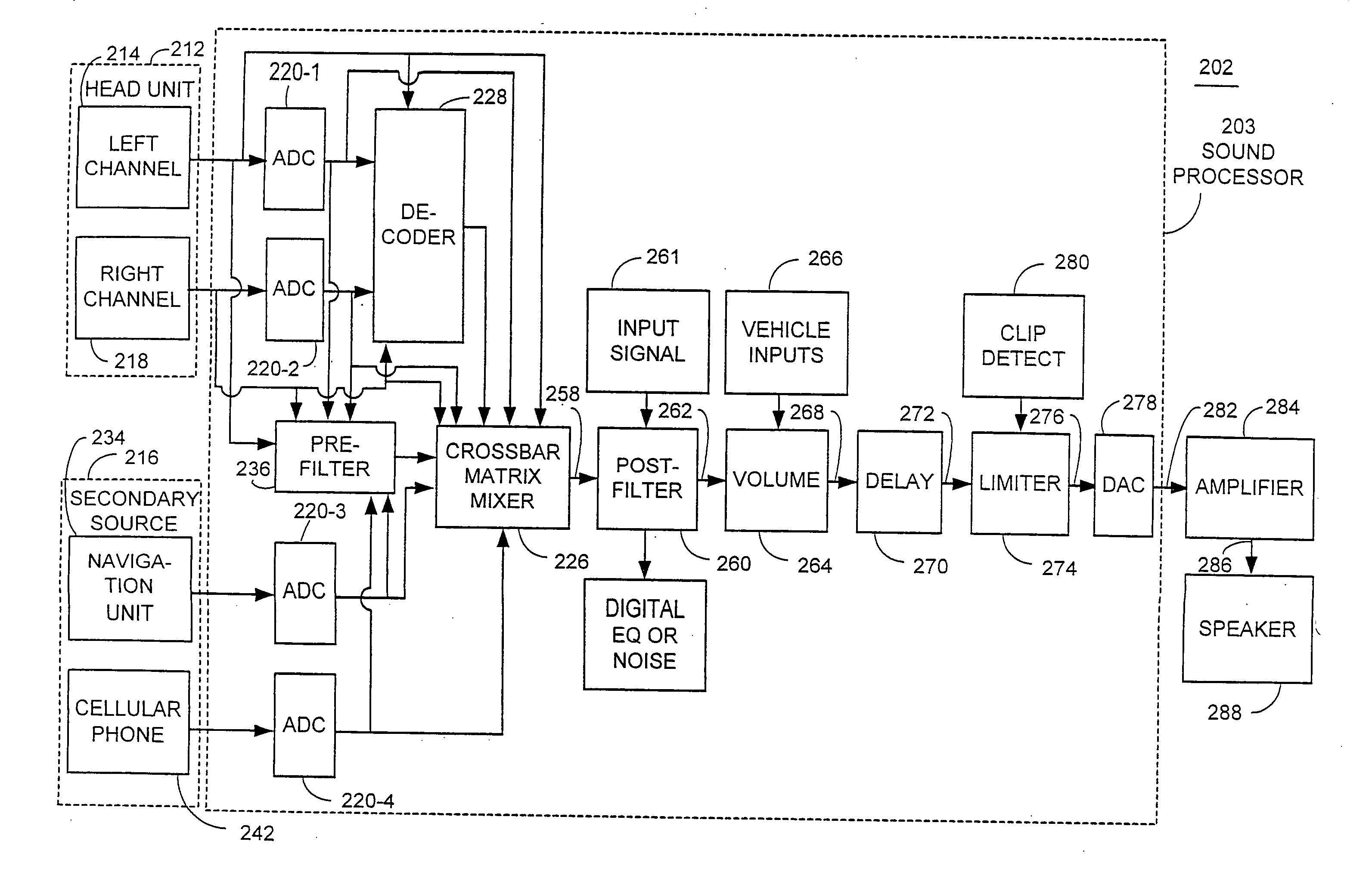
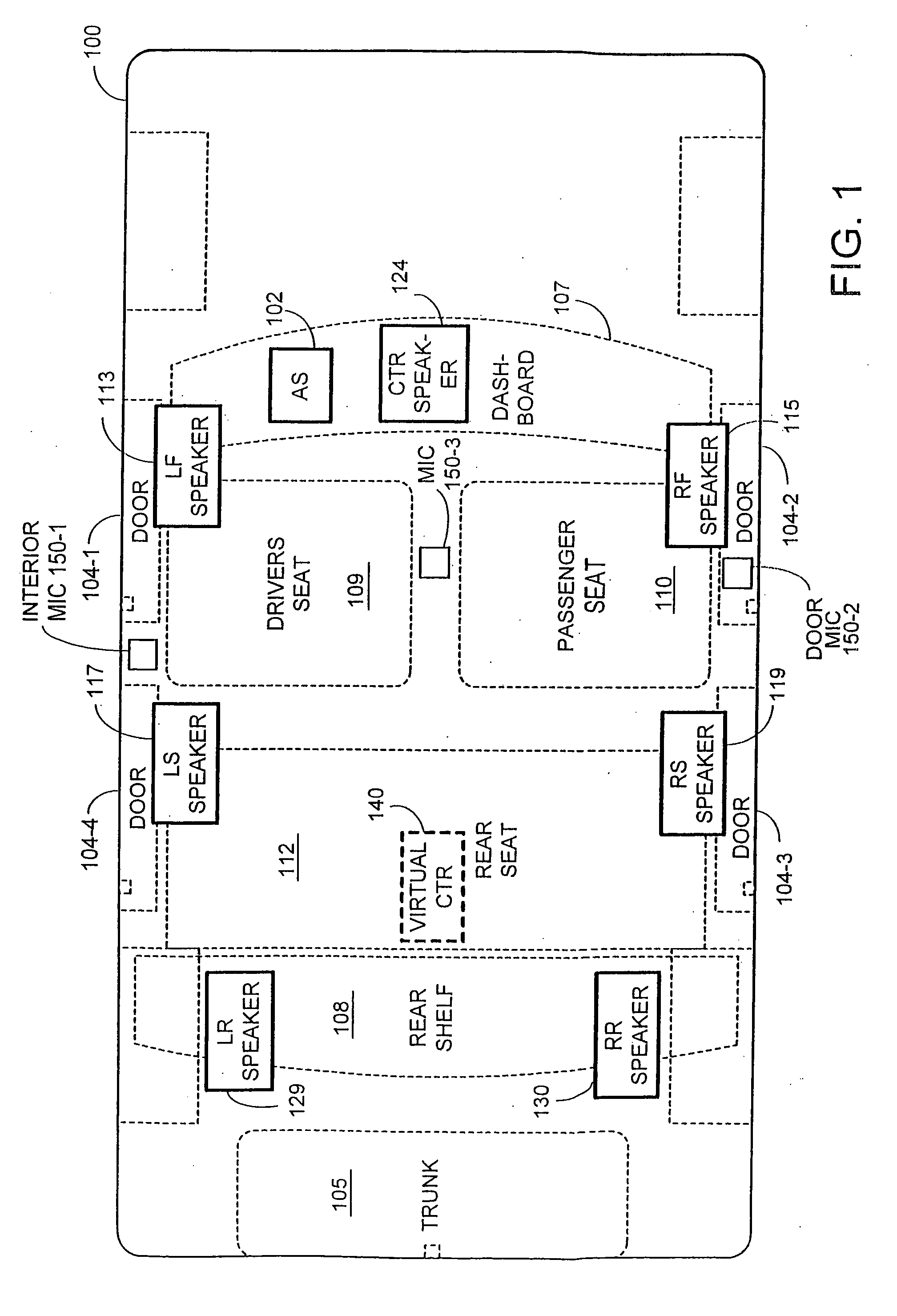
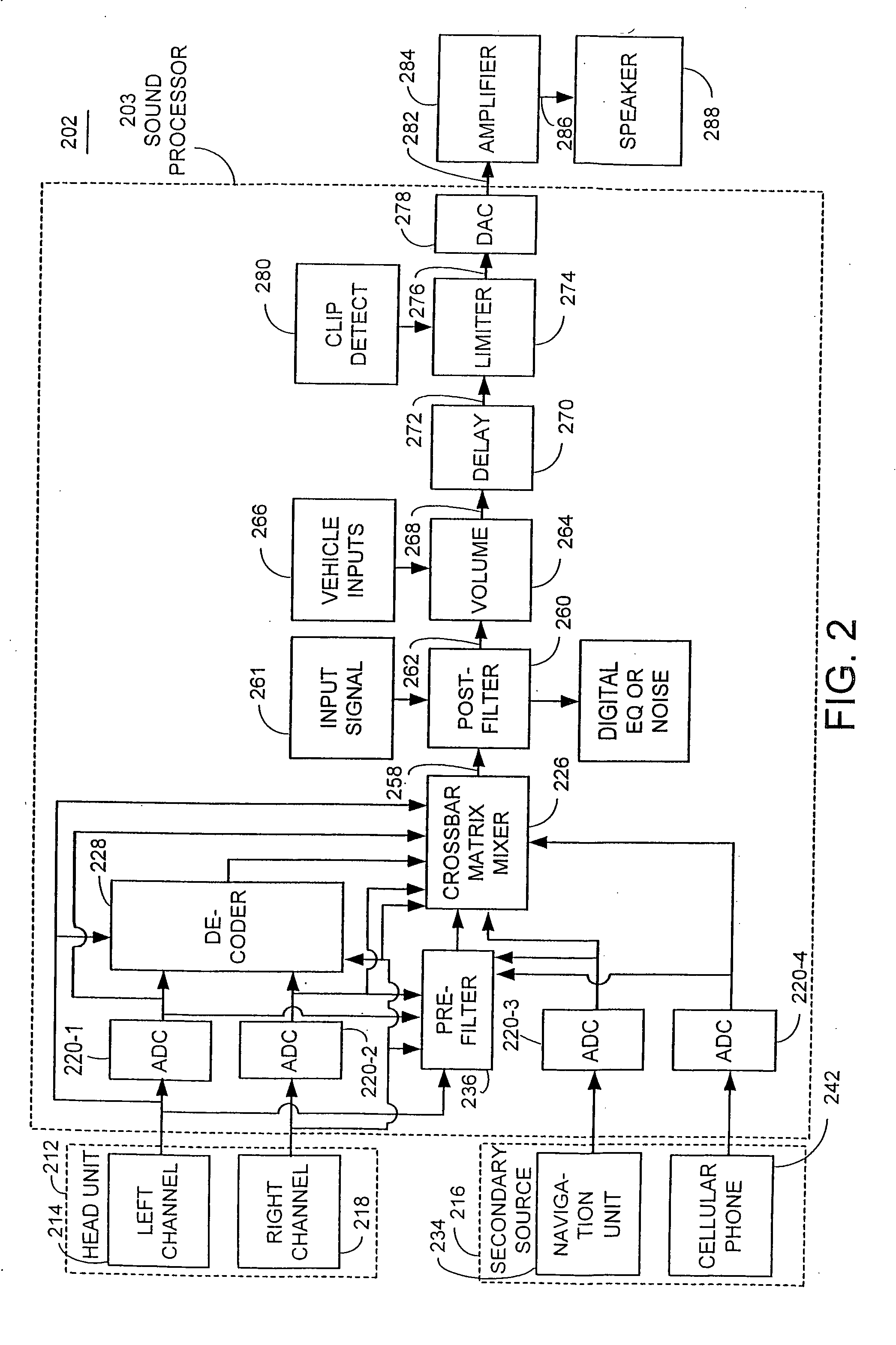
[0032]FIG. 1 is a block diagram of a vehicle 100 including an audio or sound processing system (AS) 102, which may include any or a combination of the sound processing systems and methods described below. The vehicle 100 includes doors 104, a driver seat 109, a passenger seat 110, and a rear seat 111. While a four-door vehicle is shown including doors 104-1, 104-2, 104-3, and 104-4, the audio system (AS) 102 may be used in vehicles having more or fewer doors. The vehicle may be an automobile, truck, boat, or the like. Although only one rear seat is shown, larger vehicles may have multiple rows of rear seats. Smaller vehicles may have only one or more seats. While a particular configuration is shown, other configurations may be used including those with fewer or additional components.
[0033] The audio system 102 improves the spatial characteristics of surround sound systems. The audio system 102 supports the use of a variety of audio components such as radios, CDs, DVDs, their deriva...
PUM
 Abstract
Description
Claims
Application Information