Thermally-floating transmitter wavelength grid of signal channels in a WDM transmission system

a transmission system and transmitter wavelength technology, applied in the field of optical transmission systems or networks, can solve the problems of generating a considerable amount of heat, limiting the size, power and cost of such equipment, and significantly reducing the

Active Publication Date: 2006-04-27
INFINERA CORP
View PDF16 Cites 34 Cited by
  • Summary
  • Abstract
  • Description
  • Claims
  • Application Information

AI Technical Summary

Benefits of technology

[0008] According to this invention, a method and apparatus is provided for tracking a thermally floating wavelength signal channel grid generated at an optical transmitter (Tx) in an optical transmission system or optical network where the wavelengths of the individual Tx signal channels may move in wavelength due to, for example, changes in ambient temperature at the optical transmitter but the channel spacing between adjacent Tx signal channels along the thermally floating Tx wavelength grid remains constant. An optical receiver (Rx) is provided that has a demultiplexed sig

Problems solved by technology

In a conventional dense wavelength division multiplexed (DWDM) communication system available today from telecommunication service provider equipment manufacturers, the generation of a considerable amount of heat is commonplace and is a major limitation to decreasing the size, power, and cost of such equipment.
Although this kind of integration has demonstrated reduced power consumption, the thermoelectric cooler (TEC) or a Peltier cooler are still required to cool these PIC chips and can consume up to four to ten times as much power as the chip or chips themselves that are being cooled to maintain their operation at a designated operating temperature so that the transmitter modulated sources ma

Method used


Image

  • Thermally-floating transmitter wavelength grid of signal channels in a WDM transmission system
  • Thermally-floating transmitter wavelength grid of signal channels in a WDM transmission system
  • Thermally-floating transmitter wavelength grid of signal channels in a WDM transmission system

Examples


Embodiment Construction

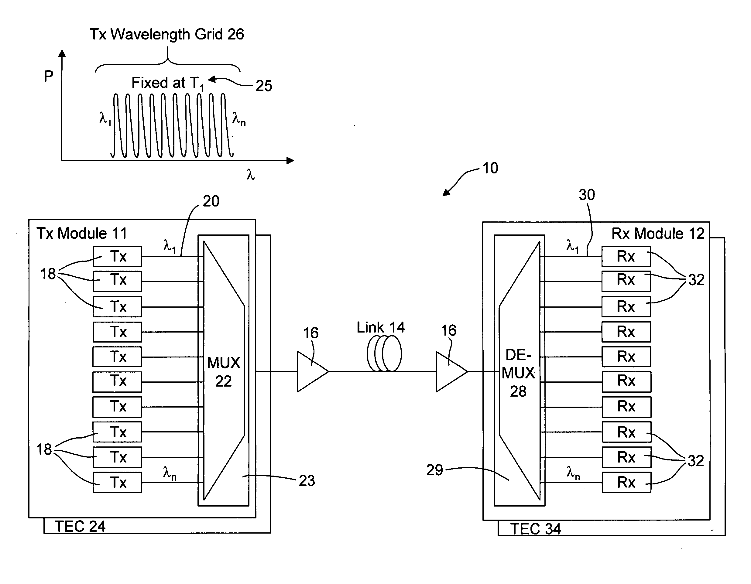
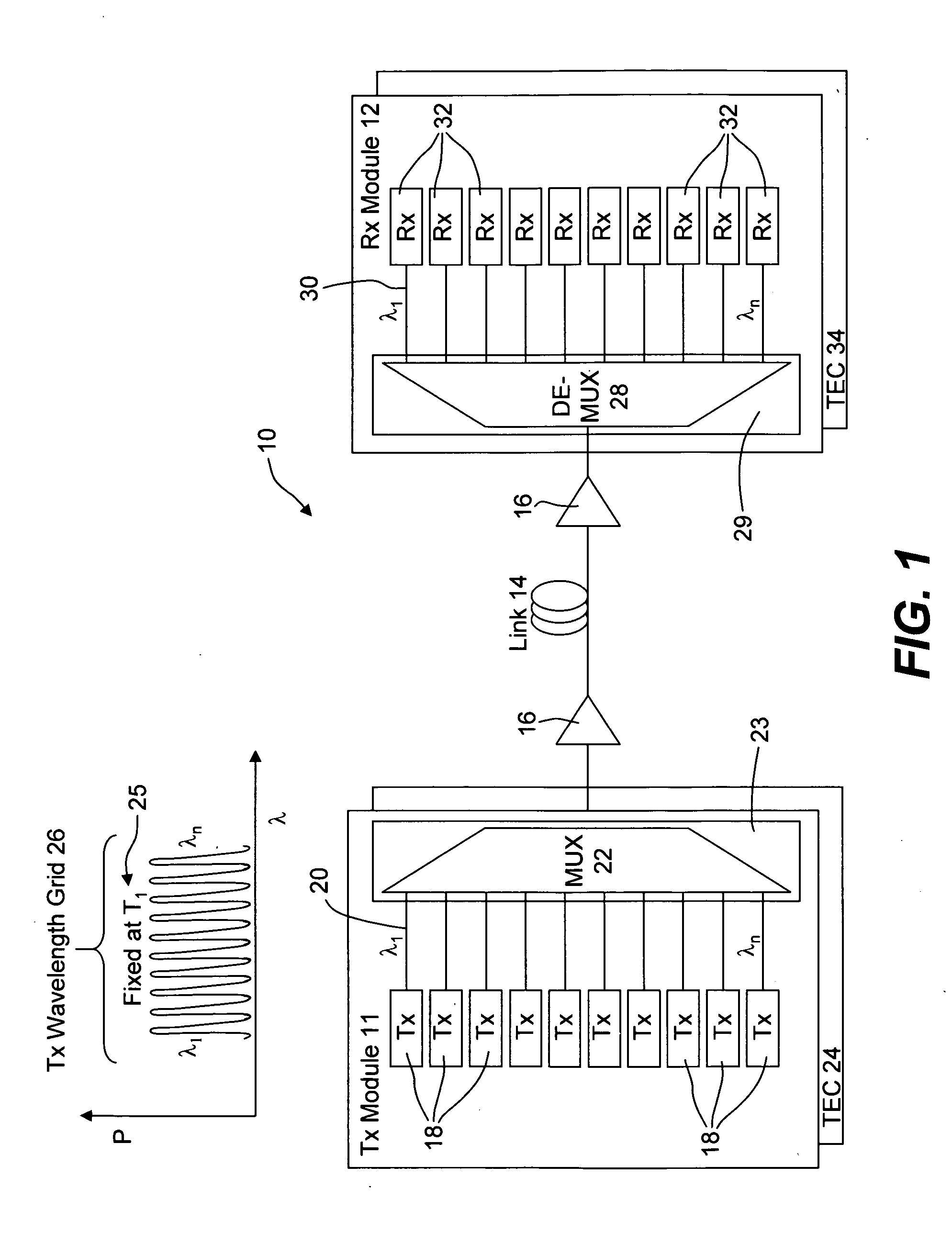
[0022] Reference is now made to FIG. 1 which illustrates a conventional wavelength division multiplexing system or optical network 10. An optical transmitter module (Tx) 11 is optically coupled to an optical receiver module (Rx) 12 via an optical medium or link 14. The link 14 may include one or more optical amplifiers 16 to amplify the multiplexed signal in its transmission over link 14. Tx module 11 includes a plurality of optical transmitters 18 which number N and each provided with a modulated source at a designated wavelength on a standardized grid, such as the ITU grid. The grid of wavelengths λ1 to λn is shown at the top of FIG. 1 at 26 where the grid wavelengths are maintained at their desired wavelengths by means of fixing the temperature at the module to T1 as indicated at 25. Each of the transmitters may be a discrete modulated source or all or some of the transmitters 18 may be integrated on a single chip as illustrated in incorporated Pub. No. US 2003 / 0095737 A1. By “mo...


PUM


Abstract

A method and apparatus is provided for tracking a thermally floating wavelength signal channel grid generated at an optical transmitter (Tx) in an optical transmission system or optical network where the wavelengths of the individual Tx signal channels may move in wavelength due to, for example, changes in ambient temperature at the optical transmitter but the channel spacing between Tx signal channels along the thermally floating Tx wavelength grid remains constant. An optical receiver (Rx) is provided that has a demultiplexed signal channel grid that may have a different channel spacing from that of the floating Tx wavelength grid, that is either larger, the same as, or smaller Rx grid spacing compared to the Tx grid spacing, and includes a number of demultiplexed channel signal outputs along an Rx channel grid in excess of the number of Tx signal channels on the Tx channel grid so that the optical receiver is capable of detecting the floating Tx channel grid and providing electrical output signals representative of the Tx channel signals transported over the optical network.

Description

REFERENCE TO RELATED APPLICATION [0001] This application claims priority of U.S. provisional patent application, Ser. No. 60 / 622,248, filed Oct. 26, 2004, which application is incorporated herein by its reference.BACKGROUND OF THE INVENTION [0002] 1. Field of Invention [0003] This invention relates generally to optical transmission systems or networks and more particularly to optical transmitters and optical receivers operated with a thermally floating wavelength grid of optical signal channels where the individual channel signals at the optical transmitter grid channels are not held to a fixed and predetermined wavelengths along a standardized wavelength grid, such as the recommended ITU wavelength grid via G.692. [0004] 2. Description of the Related Art [0005] In a conventional dense wavelength division multiplexed (DWDM) communication system available today from telecommunication service provider equipment manufacturers, the generation of a considerable amount of heat is commonpl...

Claims


Application Information

Patent Timeline
IPC IPC(8): H04J14/02
CPCH04B10/506H04B10/572H04J14/02
Inventor MORTON, PAUL A.
Owner INFINERA CORP
Why Eureka
Try Eureka