Belt drive control method, belt-drive control device, and image forming apparatus

a control method and control device technology, applied in the direction of electrographic process apparatus, instruments, optics, etc., can solve the problems of eccentricity of encoder roller detection error, angular displacement of rotational speed of rollers fluctuating, and uneven image concentration in the direction of the circumferen

Inactive Publication Date: 2006-04-27
RICOH KK
View PDF11 Cites 58 Cited by
  • Summary
  • Abstract
  • Description
  • Claims
  • Application Information

AI Technical Summary

Benefits of technology

[0018] It is an object of the present invention to solv...

Problems solved by technology

As a result, unevenness of image concentrations occurs in the direction of the circumference.
Such a problem is significant when a light-colored image of a single color is formed.
However, an angular displacement of rotational speed of rollers can fluctuate due to various factors such as eccentricity of the driven roller itself or eccentricity of attachment of the encoder to the driven roller.
A detection error due to eccentricity of the encoder roller is obtained from the angular speed information from which the speed fluctuation component due to eccentricity of the driving roller is offset.
H9-267946, when filter processing by the filter unit is performed digitally, since a large amount of calculation is required, processing time is long.
In addition, to perform such arithmetic processing, expensive hardware is necessary.
Since a conversion error occurs ...

Method used


Image

  • Belt drive control method, belt-drive control device, and image forming apparatus
  • Belt drive control method, belt-drive control device, and image forming apparatus
  • Belt drive control method, belt-drive control device, and image forming apparatus

Examples


Embodiment Construction

[0059] Exemplary embodiments of the present invention are explained below in detail with reference to the accompanying drawings.

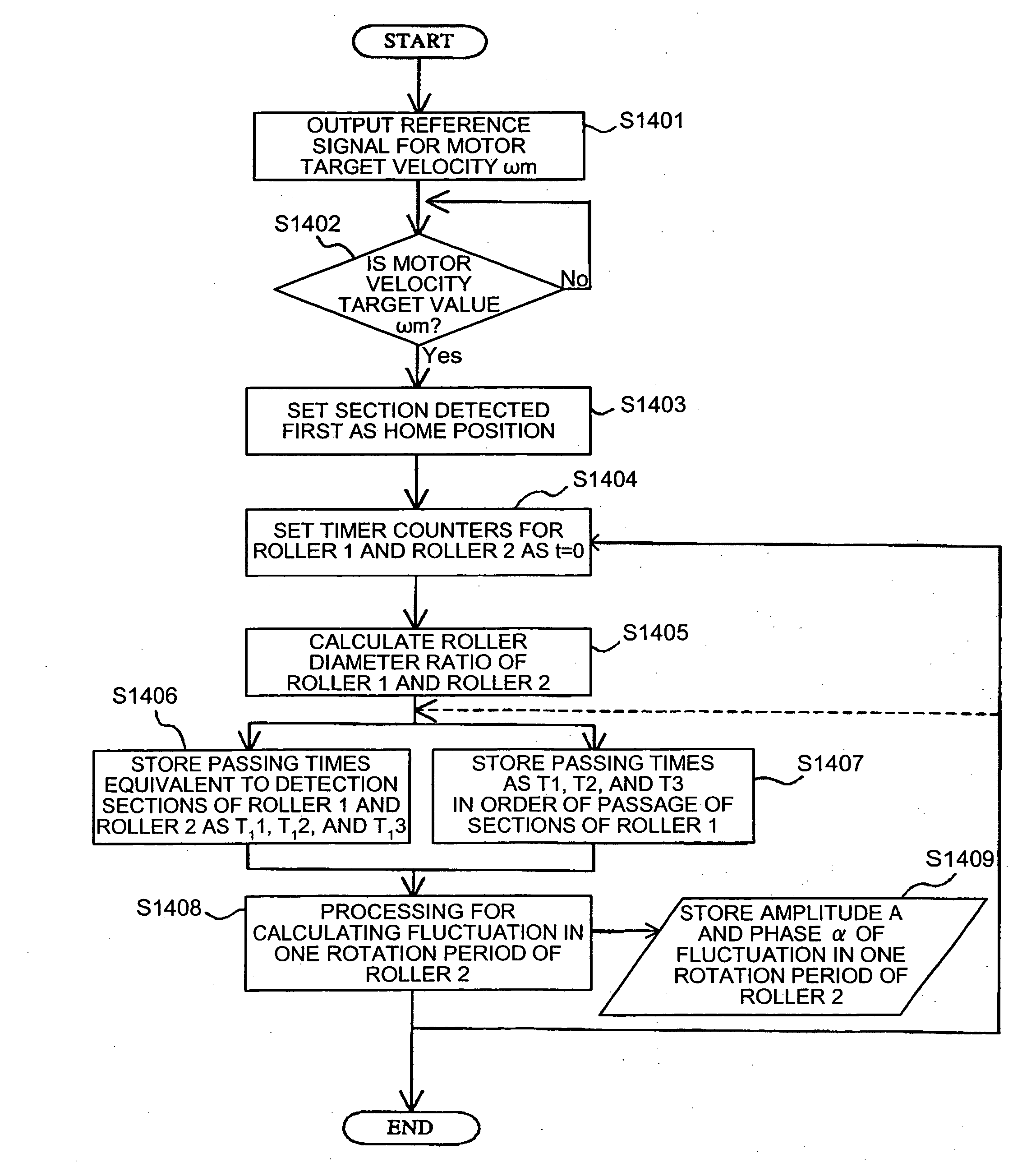
[0060] When a cause of fluctuation in a rotational speed of a target roller for speed detection is eccentricity of a rotating member and is mainly fluctuation in a rotational speed in one rotation period, the fluctuation in a rotational speed of the rotating member is expressed in a relatively simple formula including an amplitude A and a phase α of a sine wave as unknown parameters. Note that ω02 is rotational speed of the rotating member rotated along with movement of a belt.

ω2=ω02+A sin(ω02t+α)  (1)

The inventors of the present invention found that it is possible to determine the amplitude A and the phase α from equation 1 by measuring rotation times of predetermined rotation angles of the rotating member in different phases within one rotation period of the rotating member.

[0061]ω02 is calculated from rotation time during which a first support rotati...


PUM


Abstract

A rotational speed of a first roller and a time required for a second roller to make one rotation are measured. A controller calculates an amplitude and a phase of fluctuation in a rotational speed in one rotation period of the first roller while the first roller is rotated by a predefined angle based on the speed and the time. The controller corrects measured speed of the first roller based on the amplitude and the phase, and controls a driving roller based on corrected speed.

Description

CROSS-REFERENCE TO RELATED APPLICATIONS [0001] The present document incorporates by reference the entire contents of Japanese priority document, 2004-313058 filed in Japan on Oct. 27, 2004 and 2005-205379 filed in Japan on Jul. 14, 2005. BACKGROUND OF THE INVENTION [0002] 1. Field of the Invention [0003] The present invention relates to a belt drive control method and a belt-drive control device that controls drive of an endless belt wound around rollers, and an image forming apparatus that includes the belt-drive control device. [0004] 2. Description of the Related Art [0005] An image forming apparatus includes a belt such as a photosensitive belt, an intermediate transfer belt, and a paper conveyor belt. In such image forming apparatus, it is essential to control drive of the belt with high accuracy to obtain high-quality images. Particularly, for a tandem image forming apparatus of a direct transfer system that is excellent in an image forming speed and suitable for a reduction i...

Claims


Application Information

Patent Timeline
IPC IPC(8): G03G15/00
CPCG03G15/0131G03G15/1605G03G2215/0119G03G15/1615
Inventor MATSUDA, HIROMICHIKOIDE, HIROSHI
Owner RICOH KK
Why Eureka
Try Eureka