Apparatus for ejecting liquid droplet, work to be applied thereto, method of manufacturing electro-optic device, electro-optic device, and electronic equipment

a technology of liquid droplet and ejector, which is applied in the direction of lighting and heating apparatus, combustion types, instruments, etc., can solve the problem that the flushing operation cannot be carried out with respect to the actual drawing area before the drawing operation, and achieve the effect of stable drawing, high degree of accuracy and high degree of accuracy

Inactive Publication Date: 2006-04-27
SEIKO EPSON CORP
View PDF6 Cites 11 Cited by
  • Summary
  • Abstract
  • Description
  • Claims
  • Application Information

AI Technical Summary

Benefits of technology

[0007] Therefore, it is an advantage of the invention to provide an apparatus for ejecting liquid droplet in a roll-to-roll system in which a flushing operation can be carried out immediately before carrying out the drawing operation on actual drawing areas provided on roll-type work and in which stable drawing with respect to the actual drawing areas is achieved. It also provides a work to be applied thereto, a method of manufacturing an electro-optic device, the electro-optic device, and electronic equipment.
[0008] According to one aspect of the invention, there is provided an apparatus for ejecting liquid droplet for drawing a pattern on a work having a plurality of drawing areas provided in the longitudinal direction, the apparatus comprising: a suction table disposed in a drawing space for setting the work by suction; a delivering apparatus for delivering the work intermittently for introducing the work onto the suction table in a sagged state; a drawing means for drawing a pattern on the work set by suction by driving the functional liquid droplet ejection head to eject liquid droplet; a work receiving means for receiving the drawn work in a sagged state from the suction table; and a flushing unit including a flushing box for receiving ejection from the functional liquid droplet ejection head located at least at one of the sagged portions of the work.
[0009] In this arrangement, the flushing box is disposed on one of the sagged portion of the work between the delivering apparatus and the suction table, and the sagged portion of the work between the suction table and the work receiving means. Therefore, by moving the functional liquid droplet ejection head relatively with respect to the drawing space at the time of drawing process, the functional liquid droplet ejection head is faced to the flushing box for the flushing operation. In this case, since the suction table and the flushing box are arranged adjacently to each other, the functional liquid droplet ejection head can carry out the flushing operation before carrying out the drawing operation with respect to the work (drawing area) on the suction table. Therefore, in the drawing operation, the functional liquid can be ejected stably from the functional liquid droplet ejection head, whereby drawing on the drawing area with high degree of accuracy is achieved.
[0010] In this case, preferably, the work is provided with alignment marks for correcting the positions of the respective drawing areas, and an image recognition means for photographing the alignment marks and recognizing the image, and a θ-table for correcting the position in the horizontal plane of the drawing area with respect to the functional liquid droplet ejection head are further provided.
[0011] In this arrangement, since the alignment marks are provided corresponding to the respective drawing areas, θ-correction (positional correction) of the drawing area can be achieved based on the image recognition, whereby drawing with high degree of accuracy can be achieved.
[0012] In this case, the flushing box is preferably supported by the θ-table.

Problems solved by technology

However, in this case, since the work is delivered continuously, the flushing boxes cannot be disposed in the X-direction, which is the delivering direction of the work, and hence the flushing operation cannot be carried out with respect to the actual drawing areas before the drawing operation.

Method used


Image

  • Apparatus for ejecting liquid droplet, work to be applied thereto, method of manufacturing electro-optic device, electro-optic device, and electronic equipment
  • Apparatus for ejecting liquid droplet, work to be applied thereto, method of manufacturing electro-optic device, electro-optic device, and electronic equipment
  • Apparatus for ejecting liquid droplet, work to be applied thereto, method of manufacturing electro-optic device, electro-optic device, and electronic equipment

Examples


Embodiment Construction

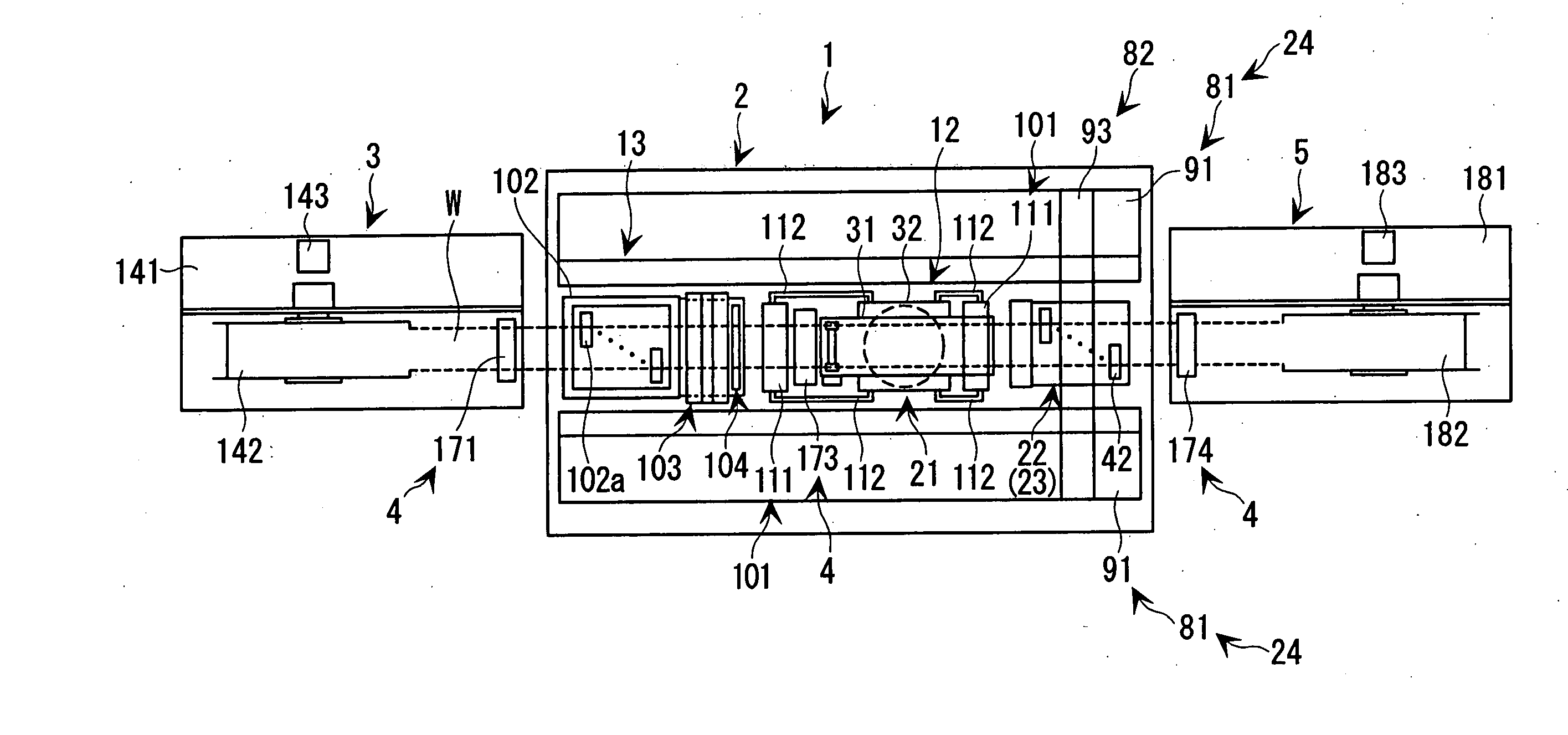
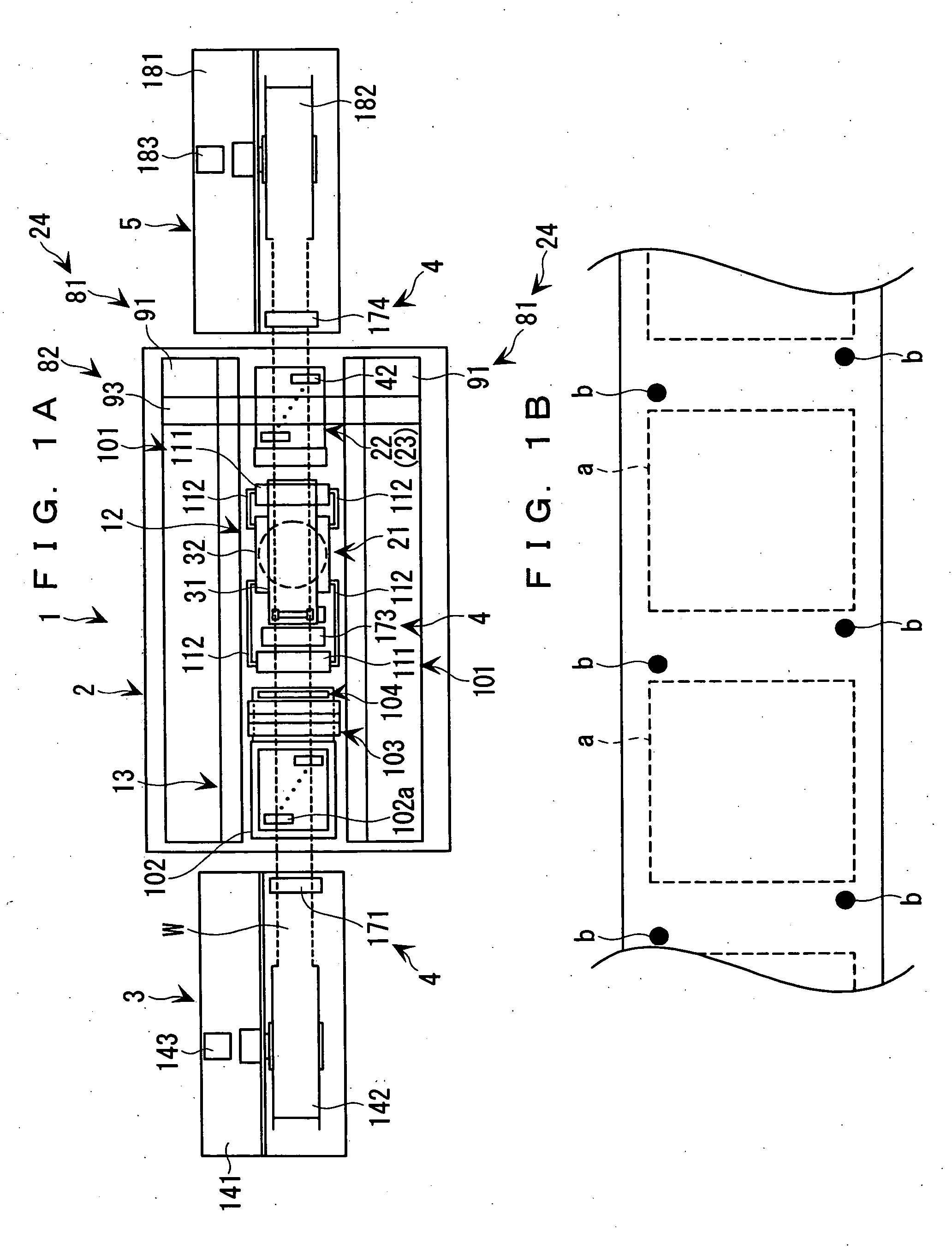
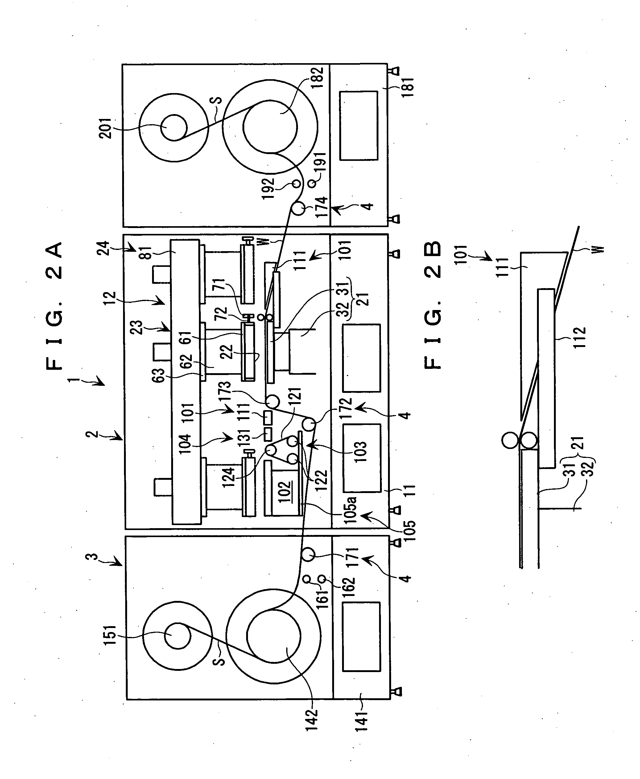
[0049] Referring now to the accompanied drawings, a description will be made about an apparatus for ejecting liquid droplet (also referred to as a liquid droplet ejection apparatus) to which the invention is applied. The liquid droplet ejection apparatus is for manufacturing a flexible board to be built in a compact camera, a mobile phone, and so on, and for forming elements such as a resistance, a coil, or a capacitor (chip part: surface-mounting part) or a metal wiring by discharging functional liquid including a function material dissolved therein on a flexible base film (work) by a fluid eject method using a functional liquid droplet ejection head.

[0050] As shown in FIGS. 1A and 2, the liquid droplet ejection apparatus 1 includes functional liquid droplet ejection heads 42, and is provided with: a drawing apparatus 2 for carrying out drawing (picturing) by the functional liquid droplet on the work W; a delivering apparatus 3 for delivering an elongated work W wound into a roll ...


PUM

PropertyMeasurementUnit
flexibleaaaaaaaaaa
suctionaaaaaaaaaa
areaaaaaaaaaaa

Abstract

An apparatus for ejecting liquid droplet includes a suction table for setting a rolled work having a plurality of drawing area arranged in the longitudinal direction by suction, a delivering apparatus for introducing the work into the suction table in a sagged state, a drawing apparatus having functional liquid droplet ejection heads for drawing patterns on respective drawing areas on the work set by suction while relatively moving the functional liquid droplet ejection heads, a winding apparatus for winding the work with the pattern drawn thereon in the sagged state, and a flushing unit having a flushing box for receiving ejection from the functional liquid droplet ejection head so as to be located in at least one of the sagged portions of the work.

Description

BACKGROUND OF THE INVENTION [0001] 1. Field of the Invention [0002] The present invention relates to an apparatus for ejecting liquid droplet for drawing (picturing) a pattern on an elongated work (or workpiece) by using a functional liquid droplet ejection head, a work to be applied thereto, a method of manufacturing an electro-optic device, an electro-optic device, and electronic equipment. [0003] 2. Description of the Related Art [0004] The apparatus for ejecting liquid droplet (also referred to as the liquid droplet ejection apparatus) includes an X-axis table for moving a suction table (set table) on which a sheet-type board (work) is mounted in the X-axis direction, a Y-axis table for moving the head unit on which a functional liquid droplet ejection head is mounted in the Y-axis direction, and is adapted in such a manner that a predetermined pattern is drawn on a board set thereon by driving the functional liquid droplet ejection head to discharge or eject while relatively mo...

Claims


Application Information

Patent Timeline
Patent Type & Authority Applications(United States)
IPC IPC(8): B05D5/12B05C5/00B05B15/12B41J2/01G02F1/13
CPCB41J3/407B41J11/0085Y10T428/24802G02B5/201G02F1/133516B41J2002/1742B41J2/165
Inventor MIYASAKA, YOICHI
Owner SEIKO EPSON CORP
Why Eureka
Try Eureka