Connector

a technology of connecting rods and connectors, applied in the direction of coupling contact members, coupling device connections, coupling parts, etc., can solve the problems of failure or defective connection, contact exposure detracting from dust proofing, and further miniaturization of connectors

Inactive Publication Date: 2006-04-27
DDK LTD
View PDF6 Cites 45 Cited by
  • Summary
  • Abstract
  • Description
  • Claims
  • Application Information

AI Technical Summary

Problems solved by technology

Moreover, depending upon customer's demands or specifications and in the case that narrower pitches of contacts are desired, it may be unavoidable that connection portions of contacts should be located on the side of a fitting opening of a housing into which a flexible printed circuit board is inserted.
On proceeding of miniaturization of electric and electronic appliances in recent years, the requirement for miniaturization has put more severe pressure on connectors to be used in such appliances, with the result that the connectors have also been further miniaturized.
However, the exposure of the contacts may detract from the dust proofing property even in the case that the miniaturization of connector is not required depending upon its intended use.
The deterioration in dust proofing property may lead to failed or defective connection.

Method used


Image

  • Connector
  • Connector
  • Connector

Examples


Embodiment Construction

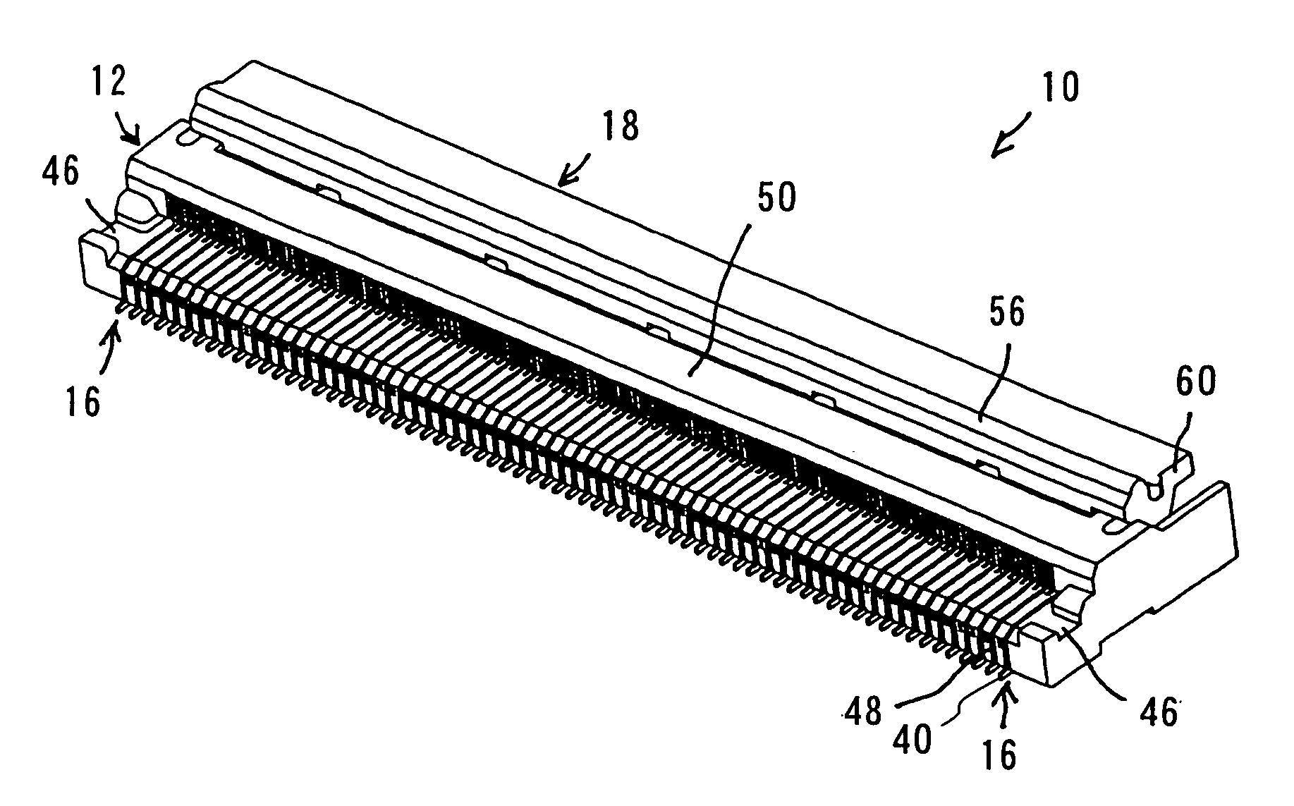
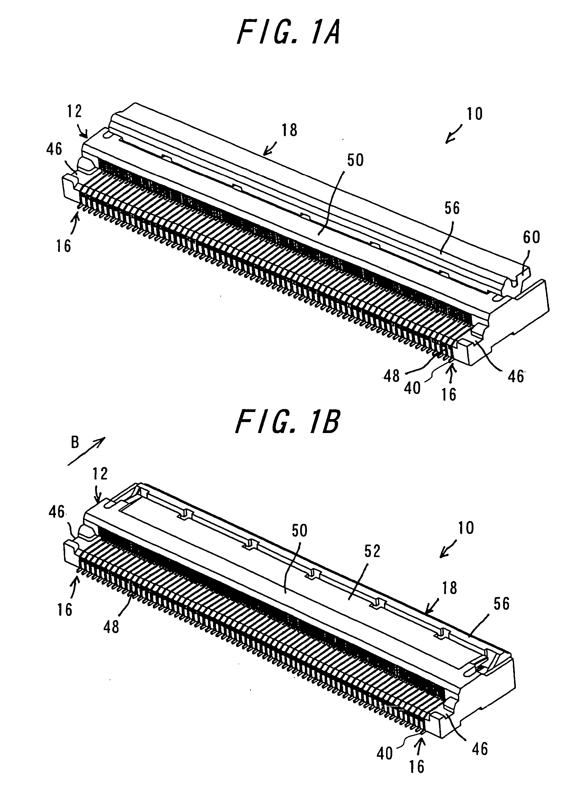
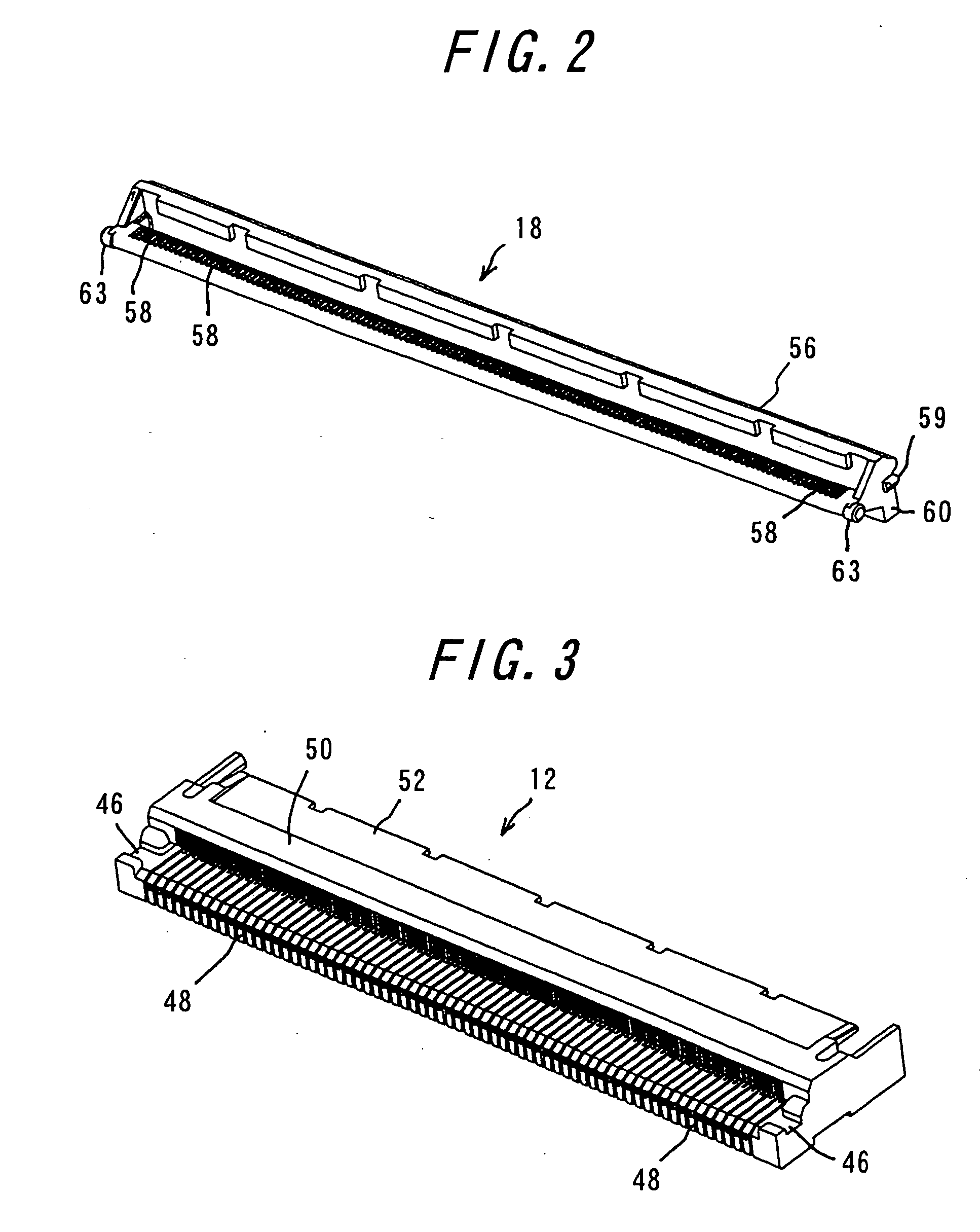
[0049] One embodiment of the invention will be explained with reference to FIGS. 1A to 7B. FIG. 1A is a perspective view of a connector according to the invention with a pivoting member opened, viewed from the side of insertion of a flexible printed circuit board, while FIG. 1B is a perspective view of the connector shown in FIG. 1A with the pivoting member closed. FIG. 2 is a perspective view of the pivoting member, and FIG. 3 is a perspective view of the housing of the connector shown in FIG. 1A. FIG. 4A is a perspective view of a contact of one kind, while FIG. 4B is a perspective view of a contact of the other kind. FIG. 5A is a sectional view of the connector taken along the contact of the one kind with the pivoting member opened, while FIG. 5B is a sectional view of the connector similar to FIG. 5A with the pivoting member closed. FIG. 6A is a sectional view of the connector taken along the contact of the other kind with the pivoting member opened, while FIG. 6B is a sectional...


PUM


Abstract

A connector includes a required number of contacts, a housing, and a pivoting member. The contacts are substantially H-shaped and each includes at least a contact portion, a connection portion, a fulcrum portion, a connecting portion and a pressure receiving portion. The urging portions of the pivoting member are pivotally moved between the connection portions and the pressure receiving portions to bring the contact portions of the contacts into contact with a connecting object. The housing has a ceiling portion covering the contact portions of the contacts, and an upper wall covering the pressure receiving portions. The pivoting member includes an actuating portion, the urging portions, anchoring holes, and a cover portion for covering tail portions of the contacts upon pivotal movement of the pivoting member. The connecting object can be inserted into the connector with a slight force and dust proofing property can be improved.

Description

BACKGROUND OF THE INVENTION [0001] This invention relates to a connector using a flexible printed circuit board for use in electric or electronic appliances such as thin type plasma displays or televisions, notebook personal computers and the like, and more particularly to a dust-proof connector. [0002] In general, connectors for use in mobile phones, charge coupled device (CCD) cameras and the like are much thinner and having contacts arranged in extremely narrow pitches (so-called lighter and more compact connector). A connector of one type mainly comprises a housing and contacts, and a flexible printed circuit board is inserted into the housing to bring the circuit board into contact with contact portions of the contacts (so-called “non-zero-insertion force (NZIF)” type). Moreover, another type connector mainly comprises a housing, contacts and a slider so that a flexible printed circuit board is embraced between the housing and the slider (so-called “zero-insertion force (ZIF)” ...

Claims


Application Information

Patent Timeline
Patent Type & Authority Applications(United States)
IPC IPC(8): H01R13/15
CPCH01R12/771H01R12/88H01R13/193
Inventor TAKAI, MASATAKEFUKAZAWA, TAKEKIYOSHIMI, TAKANOBU
Owner DDK LTD
Why Eureka
Try Eureka