Method of forming multi-colored composite by pinsonic embossing

a multi-colored composite and pinsonic technology, applied in the field of multi-colored composites, can solve the problems of not providing a depth aspect to the appearance of the surface, possessing numerous limitations, and forming certain colors

Active Publication Date: 2006-04-27
FREUDENBERG VLIESSTOFFE
View PDF25 Cites 48 Cited by
  • Summary
  • Abstract
  • Description
  • Claims
  • Application Information

AI Technical Summary

Problems solved by technology

This provides a two-dimensional effect on the surface but does not provide a depth aspect to the appearance of the surface.
While lasers are useful in this regard, they possess numerous limitations in that only certain colors may be formed.
Further, the ablation process that takes place when a plastic is exposed to laser energy may result in significant charring and deterioration of the polymer into smoke and gummy residue.
Particularly with layered fibrous materials, lasers may be difficult to focus to allow accurate removal of a top layer.

Method used


Image

  • Method of forming multi-colored composite by pinsonic embossing
  • Method of forming multi-colored composite by pinsonic embossing
  • Method of forming multi-colored composite by pinsonic embossing

Examples


first embodiment

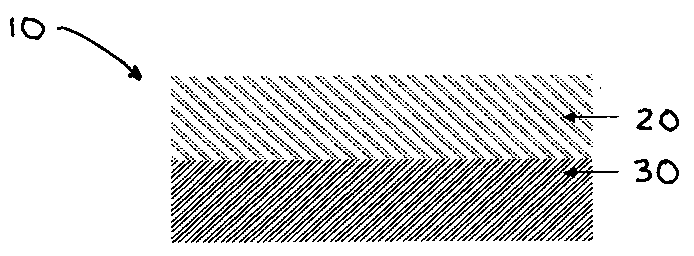
[0022] For elements common to the various embodiments of the invention, the numerical reference character between the embodiments is held constant, but distinguished by the addition of an alphanumeric character to the existing numerical reference character. In other words, for example, an element referenced at 10 in the first embodiment is correspondingly referenced at 10A, 10B and so forth in subsequent embodiments. Thus, where an embodiment description uses a reference character to refer to an element, the reference character applies equally, as distinguished by alphanumeric character, to the other embodiments where the element is common.

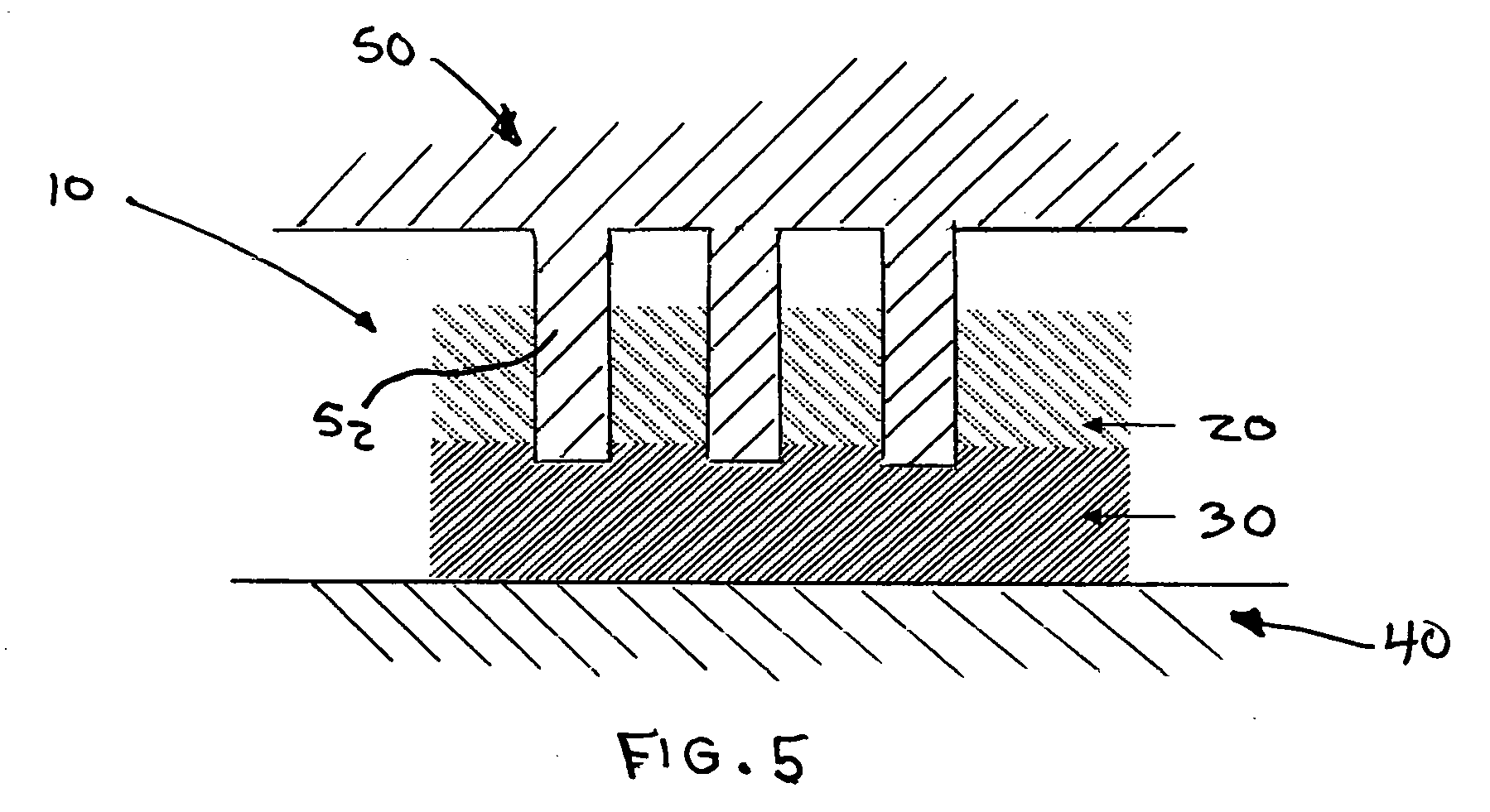
[0023] The use of ultrasonic energy to bond plastic materials together is well known. Similar or even dissimilar plastics may be joined through the use of heat generated from high frequency mechanical motion. The two plastic articles are placed one upon the other in a holding fixture and a titanium or aluminum component called a horn is brought in...

second embodiment

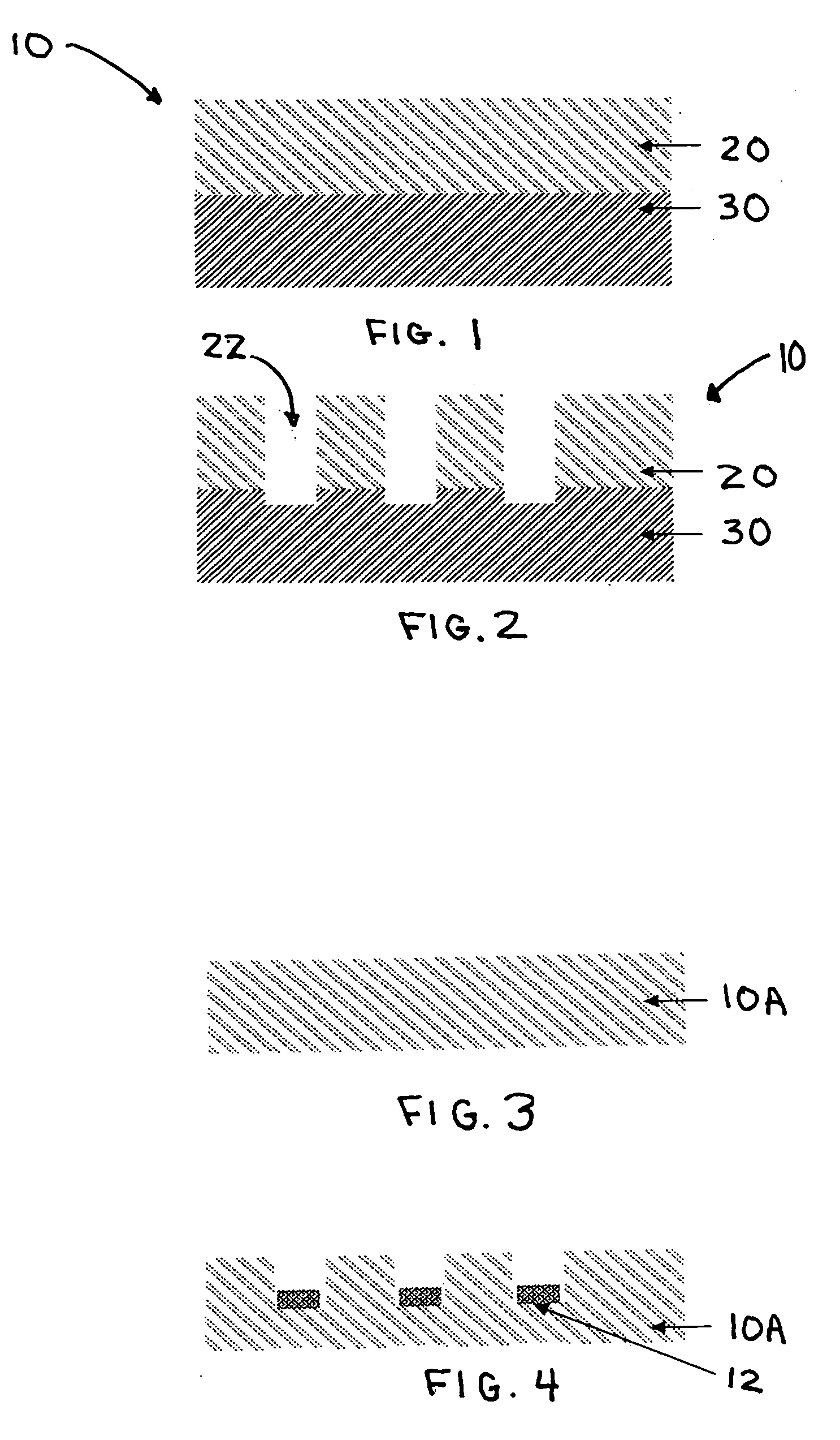
[0033] the present invention is illustrated in FIGS. 3 and 4. Here, a somewhat higher density non-woven layer 10A is provided (for instance, between about 1 and about 11 ounces / square yard). An ultrasonic horn, having a predetermined, decorative pattern, preferably of pins or projections provided on the surface, engages with the upper portion of layer 10A. Upon activation of the ultrasonic energy into the layer, a portion of the layer is melted and densifies or contracts to form a pattern 12 of densified polymer having a different color than that of the original fibrous layer 10A that has not been acted upon by the horn. The densified pattern 12 may be of a different color due to the increased density, due to melting of the polymer and pigments or dyestuffs which color the layer 10A.

[0034] In a related embodiment, heat activatable (thermochromic) pigments or dyestuffs may be used to color layer 10A which when acted upon by the ultrasonic energy are heated to a temperature which caus...


PUM

PropertyMeasurementUnit
vibration frequencyaaaaaaaaaa
frequencyaaaaaaaaaa
frequencyaaaaaaaaaa

Abstract

A method of forming a multi-colored multi-layered non-woven composite includes the application of ultrasonic energy to the top layer to displace a portion of that layer in a predetermined pattern such that openings are formed through which any underlying layer may be visible. In related embodiments, the use of pinsonic or ultrasonic embossing of a non-woven layer provides a three-dimensional colored pattern due to melting and densification of the fibers and/or the activation of heat activatable pigments or dyes used to color the non-woven.

Description

FIELD OF INVENTION [0001] This invention relates to multi-colored composites and, more particularly, to forming a multi-colored multi-layered composite by pinsonic embossing. BACKGROUND OF THE INVENTION [0002] Multi-colored decorative surfaces are desirable to differentiate products in many industries. Automotive interior trim, furniture, clothing, house sundries and many other products may benefit by providing surfaces which are more pleasing, and decorative or which have indicia, logos or personalized distinctive markings thereupon. [0003] While such processes as painting and co-molding may provide a solution for providing multi-colored solid articles, heretofore cloth or fabric articles have been colored by dyeing and printing. This provides a two-dimensional effect on the surface but does not provide a depth aspect to the appearance of the surface. [0004] One means of providing a multi-colored product involves providing two or more layers and removing the top layer(s) to expose ...

Claims


Application Information

Patent Timeline
Patent Type & Authority Applications(United States)
IPC IPC(8): B31B1/60B32B5/26D04H13/00B29C65/00B32B37/00D04H1/54
CPCB29C65/08Y10T156/10B29C66/45B29K2105/0854B29K2995/0021B29L2009/00B32B3/266B32B3/30B32B5/022B32B5/06B32B5/245B32B5/26B32B7/045B32B38/06B32B2250/02B32B2305/20B32B2307/31B32B2307/4026B32B2307/404B32B2310/028B32B2437/00B32B2601/00B32B2605/003B44C3/005B44C3/046D04H13/007B29C66/8322B29C66/21B29C66/729B29C66/73921D04H1/4374D04H1/559B29C66/1122B32B7/05Y10T442/69Y10T442/659Y10T442/60
Inventor LEIDIG, ERICHSTUPPY, GERHARD
Owner FREUDENBERG VLIESSTOFFE
Why Eureka
Try Eureka