
System and method for terrain feature tracking

Inactive Publication Date: 2006-04-27
IROBOT CORP
View PDF41 Cites 98 Cited by
  • Summary
  • Abstract
  • Description
  • Claims
  • Application Information

AI Technical Summary

Benefits of technology

[0005] The present invention provides a system and method for tracking one or more terrain features by an autonomous vehicle. While operating autonomously, the vehicle uses its on-board local area sensors and its perceptual context software to d

Problems solved by technology

This requires considerable effort by the operator, a significant investment in skilled operator training, and places severe limitations on mission duration and objectives.
In a typical environment, a vehicle can encounter any number of unforeseen hazards.
A vehicle can also create or exacerbate a hazard.
In either case, there is the potential that the vehicle may endanger persons or property.
This additional safety concern negatively affects mission effectiveness because it directs the operator's attention away from the particulars of the task the vehicle is performing.
Additionally, an operator may become overwhelmed by the degree of oversight and attention required and may fail to recognize one or more obstacles or hazards in the path of the vehicle, potentially resulting in an accident.

Method used


Image

  • System and method for terrain feature tracking
  • System and method for terrain feature tracking
  • System and method for terrain feature tracking

Examples


Embodiment Construction

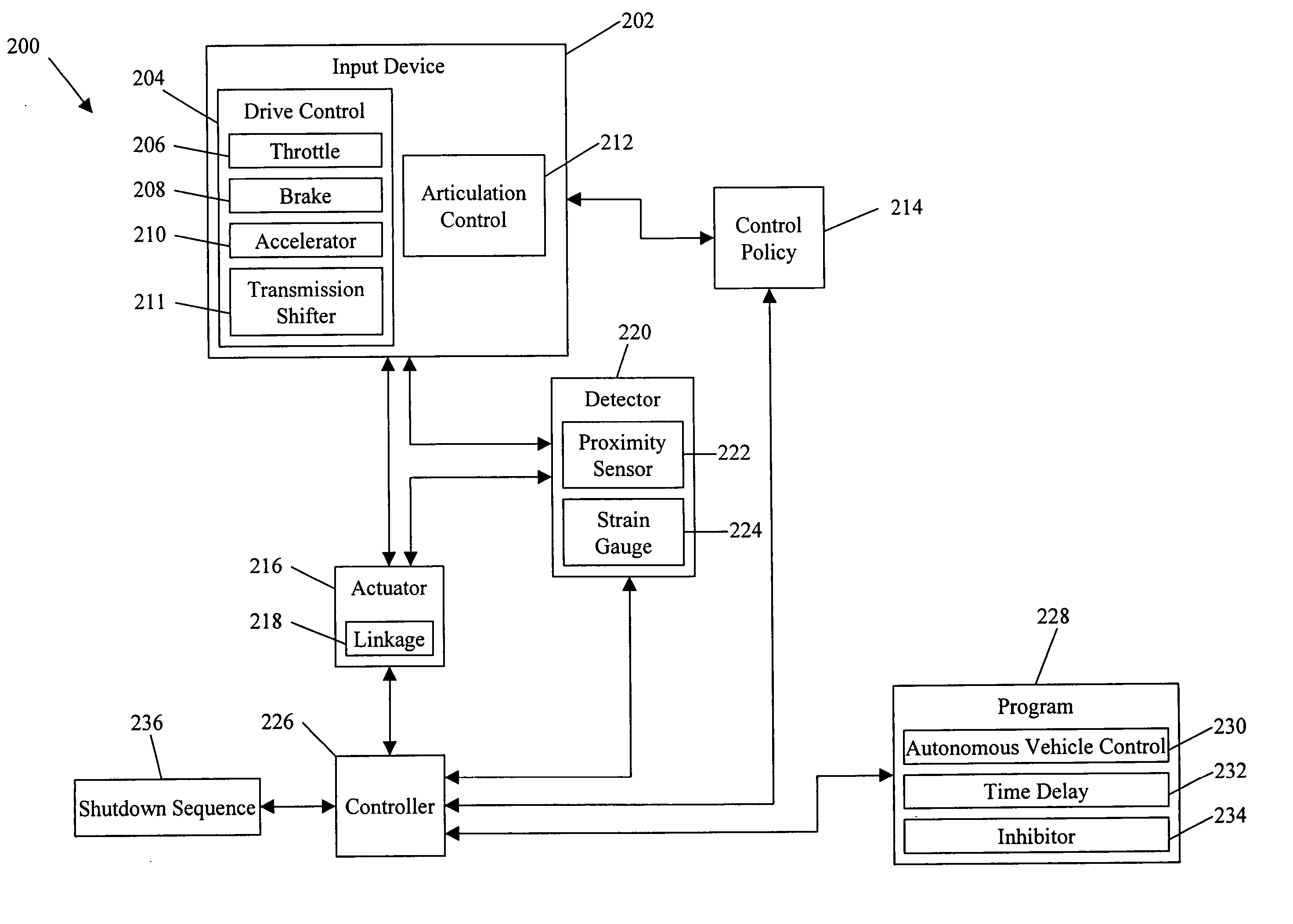
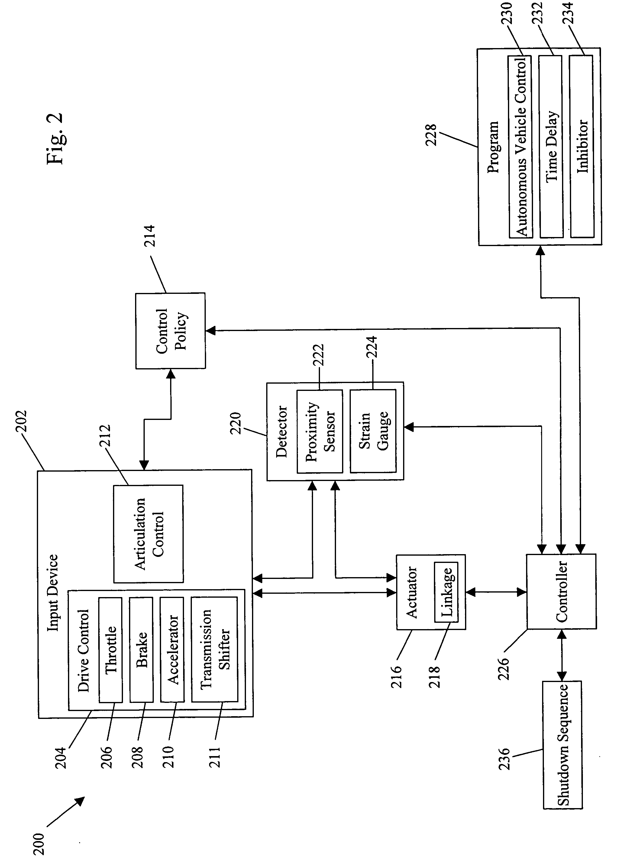
[0021] As shown in the drawings for the purposes of illustration, the invention may be embodied in systems and methods for controlling vehicles, where the systems and methods compensate, with little or no operator intervention, for changes in the environment around the vehicle. Embodiments of the invention enhance overall mission effectiveness and operating safety.

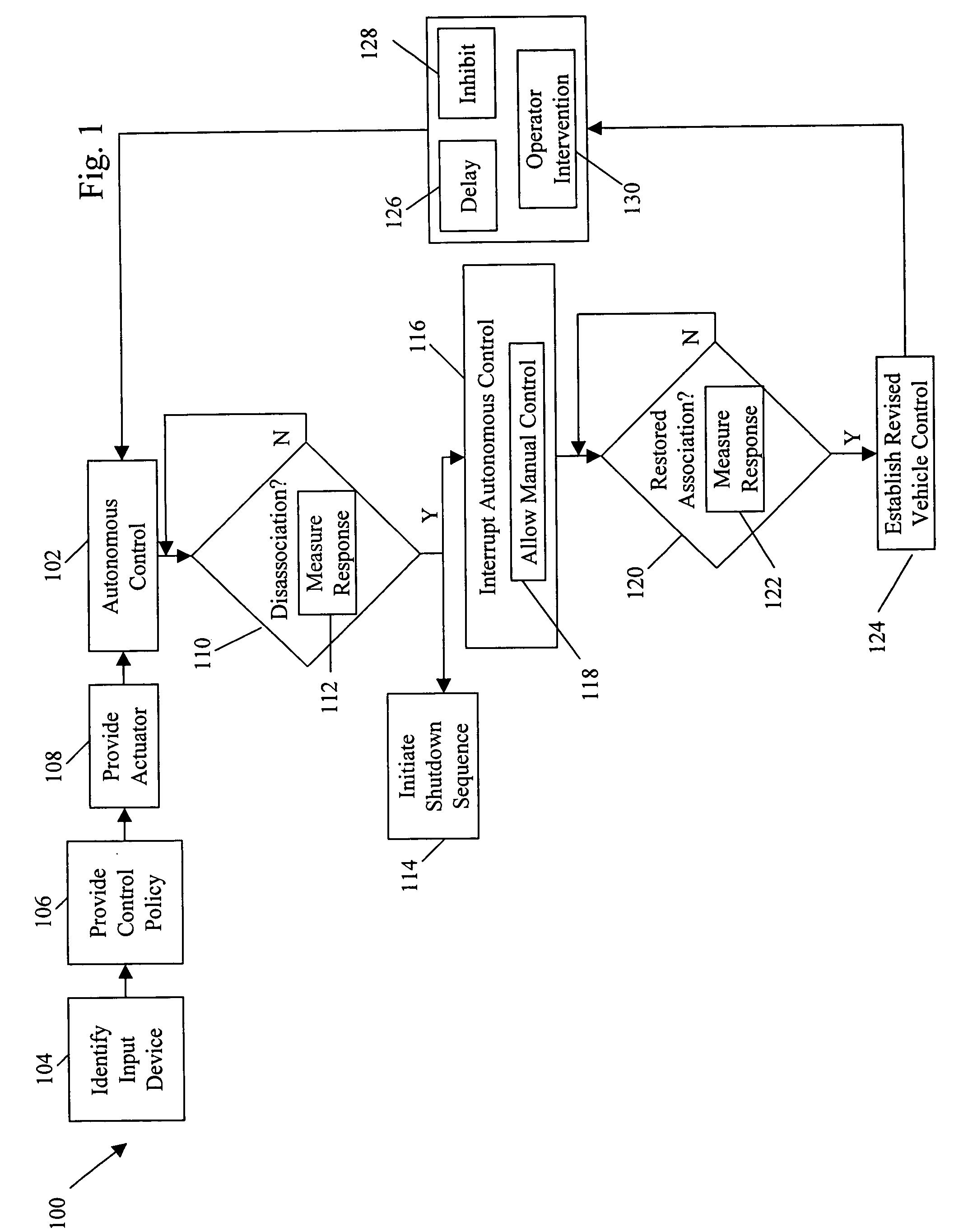
[0022] In brief overview, FIG. 1 is a flowchart depicting a method 100 for interruptible autonomous control of a vehicle in accordance with an embodiment of the invention. The method includes a step of first identifying one or more input devices in the vehicle (STEP 104). An input device may be an operator input device that directs at least part of the vehicle (e.g., one or more of a steering wheel, handle, brake pedal, accelerator, or throttle). The input device also may be a device directly or indirectly connecting the operator input device to a controlled element (i.e., the object in the autonomous vehicle ultimately c...


PUM


Abstract

System and method for tracking obstacles by an autonomous vehicle. Localization sensors (i.e., sensors to measure pitch, roll, and yaw, and systems including an inertial navigation system, a compass, a global positioning system, or an odometer) detect the position of the vehicle. Perception sensors (e.g., LIDAR, stereo vision, infrared vision, radar, or sonar) assess the environment about the vehicle. Using these sensors, locations of terrain features relative to the vehicle are computed and kept up-to-date. The vehicle trajectory is adjusted to avoid terrain features that are obstacles in the path of the vehicle.

Description

FIELD OF THE INVENTION [0001] The present invention relates generally to control of unmanned ground vehicles and, more specifically, to variations in the control of unmanned ground vehicles in response to environmental changes or operator intervention. BACKGROUND OF THE INVENTION [0002] Vehicles and equipment that operate with little or no operator intervention are desirable partly because they remove the operator from harm's way in dangerous applications and because they offer direct labor cost savings in commercial applications. In many instances, this limited intervention is exemplified by an operator removed from the confines of the vehicle itself and placed in a location with a remote control device that interfaces with and controls the vehicle. In this configuration, however, the operator typically must directly and continuously monitor the vehicle and its surrounding environment, adjusting, for example, vehicle speed and direction, as needed. In particular, when a task is com...

Claims


Application Information

Patent Timeline
IPC IPC(8): G06F17/00
CPCG01S13/726G01S13/931G05D1/024G05D1/0242G05D1/0248G05D1/0251G05D1/0255G05D1/0257G05D1/027G05D1/0272G01S2013/9321G01S2013/9342G01S2013/9346G01S2013/935G01S2013/9353G01S2013/9318G01S2013/9319G01S2013/93185G01S2013/932
Inventor FILIPPOV, MISHAALLARD, JAMESBARRETT, DAVID S.PACK, ROBERT TODDSVENDSEN, SELMA
Owner IROBOT CORP
Learn More