Press molding apparatus and method of producing a glass optical element using the apparatus

a technology of glass optical elements and press molding, which is applied in the direction of glass making apparatus, glass shaping apparatus, instruments, etc., can solve the problems of insignificant thermal uniformity, difficult to uniformly heat the molding surfaces in the single-line arrangement, and disadvantageous single-line arrangement of molding surfaces, so as to increase the temperature elevation rate of pressing molds

Inactive Publication Date: 2006-05-04
HOYA CORP
View PDF22 Cites 11 Cited by
  • Summary
  • Abstract
  • Description
  • Claims
  • Application Information

AI Technical Summary

Benefits of technology

[0013] It is therefore an object of this invention to provide a press molding apparatus and a method of producing a glass optical element which are capable of increasing a temperature elevation rate of a pressing mold.
[0014] It is another object of this invention to provide a press molding apparatus and a method of producing a glass optical element which are capable of improving thermal uniformity in a pressing mold.
[0015] It is still another object of this invention to provide an apparatus and a method for producing a glass optical element which are high in accuracy and productivity.

Problems solved by technology

Heating of the molding surfaces under the same condition (i.e., thermal uniformity) is a problem which is not negligible.
However, the single-line arrangement of the molding surfaces is disadvantageous in the following respect.
Specifically, it is difficult to uniformly heat the molding surfaces in the single-line arrangement.
Generally, it is difficult to uniformly distribute the heat from the heat source to a plurality of molding surfaces arranged in a single line so that the molding surfaces are heated under the same condition.
Such difficulty is encountered by any kind of heat source.
For example, even in case where a high-frequency induction heating apparatus extremely high in heat efficiency and high in responsiveness upon temperature elevation and temperature drop (i.e., high in productivity) is used, it is not easy in actual design to arrange the induction heating coil so that all molding surfaces are heated under the same condition.

Method used


Image

  • Press molding apparatus and method of producing a glass optical element using the apparatus
  • Press molding apparatus and method of producing a glass optical element using the apparatus
  • Press molding apparatus and method of producing a glass optical element using the apparatus

Examples


first embodiment

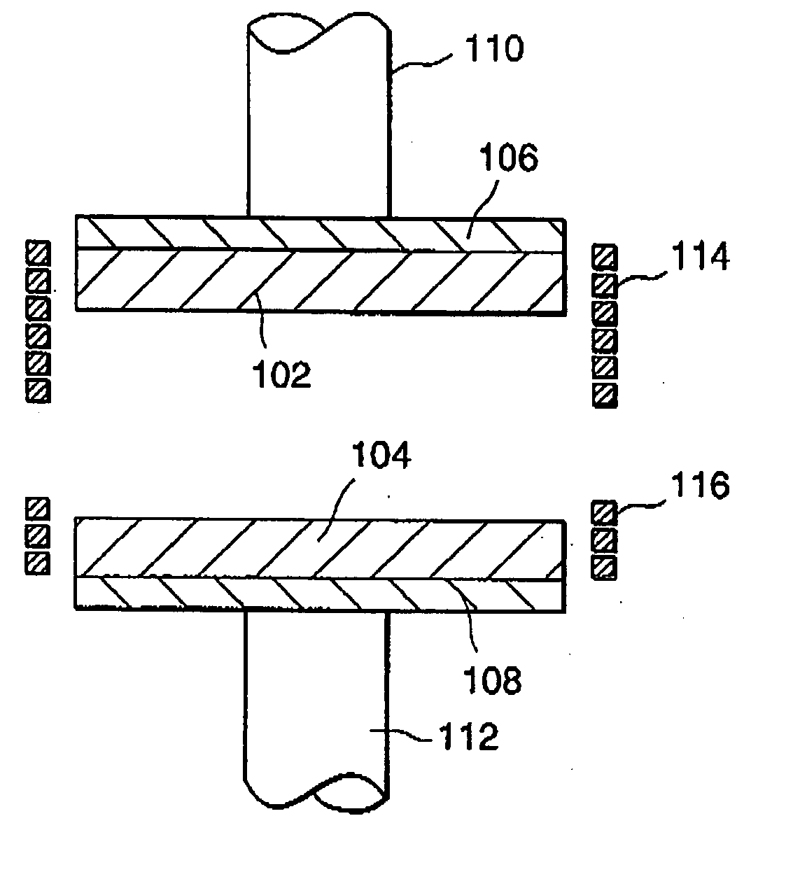
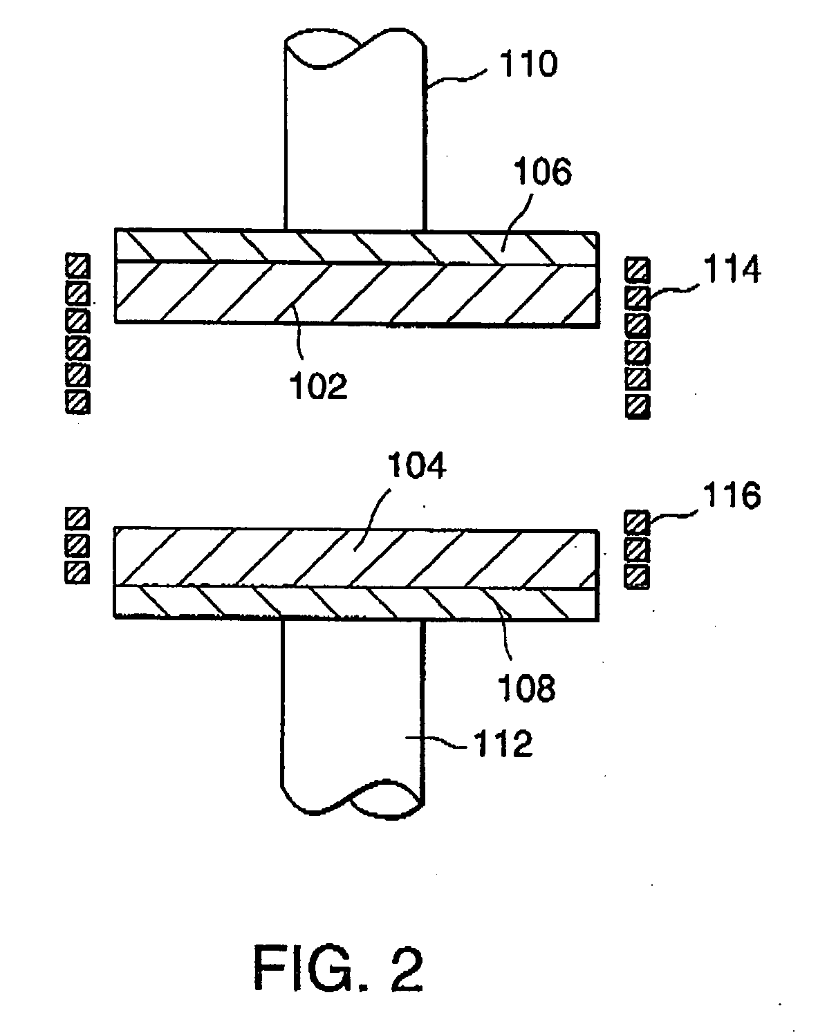
[0043] At first referring to FIG. 2, a press molding apparatus according to this invention will be described. For example, the press molding apparatus is used to produce a medium-aperture lens having a diameter of 17 mm by the use of a preform having a flat spherical shape. The press molding apparatus has a pressing mold comprising an upper mold 102 and a lower mold 104 for clamping and pressing the preform. Each of the upper and the lower molds 102 and 104 has an elongated shape extending in a transversal or horizontal direction in the figure and is made of, for example, a tungsten alloy. The upper and the lower molds 102 and 104 have a plurality of molding portions (which will later be described) formed on confronting surfaces thereof, respectively, to provide preforms with a predetermined shape. The upper and the lower molds 102 and 104 are attached through supporting members 106 and 108 to upper and lower main shafts 110 and 112, respectively, on the sides opposite to the confro...

second embodiment

[0056] Referring to FIG. 7, a press molding apparatus comprises a mother mold 600 having an elongated shape and six pairs of upper and lower mold members 602 and 604 supported by the mother mold 600 to be vertically movable. Each of the upper and the lower mold members 602 and 604 is made of cemented carbide and has a molding surface (i.e., a surface for pressing a preform P) coated with a thin film of a precious metal alloy. The mother mold 600 is made of a tungsten alloy and has a thermal expansion coefficient slightly greater than that of cemented carbide. The mother mold 600, the upper mold members 602, and the lower mold members 604 are supported on a tray 606 and transferred into a forming chamber (not shown). Between each of the lower mold members 604 and the tray 606, a spacer 608 is inserted to adjust the thickness of each lens. The tray 606 is mounted on a lower main shaft 612 driven in the vertical direction by a motor mechanism (not shown). By moving the lower main shaf...

fourth embodiment

[0066] As a specific example for the fourth embodiment, press molding was performed by the use of the press molding apparatus in which the perforations were formed throughout an entire periphery of the mother mold and particularly densely formed in the local regions corresponding to the areas between every adjacent ones of the molding surfaces (see FIG. 5). As a result, it was possible to shorten the time before the target temperature (Table 1) was reached.

[0067] Next referring to FIG. 12, description will be made of a fifth embodiment of this invention. For example, a press molding apparatus according to the fifth embodiment is used to produce a medium-aperture lens having a diameter of 17 mm by the use of a preform prepared by preliminarily forming a glass material into a flat spherical shape. As illustrated in FIG. 12, the press molding apparatus comprises a pressing mold set including an upper mold 102 and a lower mold 104. Each of the upper and the lower molds 102 and 104 has a...


PUM

PropertyMeasurementUnit
viscosityaaaaaaaaaa
viscosityaaaaaaaaaa
diameteraaaaaaaaaa

Abstract

In a press molding apparatus for press molding a plurality of glass materials into a plurality of glass optical elements by the use of a pressing mold including upper and lower molds each of which has a plurality of molding surfaces, at least one of the upper and the lower molds is a heat generator within which heat is generated when the heat generator is subjected to a high-frequency induction heating by an induction heating coil. The heat generator having a plurality of shape-processed portions (130) produced by partially processing a shape of the heat generator in order that a temperature distribution of the heat generator is adjusted. The apparatus simultaneously press forms, into the glass optical elements, the glass materials supplied between the molding surfaces of the upper and the lower molds which are subjected to the high-frequency induction heating.

Description

BACKGROUND OF THE INVENTION [0001] This invention relates to production of a glass optical element such as an optical lens and, in particular, to a press molding apparatus for press molding a preform (obtained by preliminarily forming a glass material) in a heated and softened state to provide a predetermined shape. This invention also relates to a method of producing a glass optical element by the use of the above-mentioned press-forming apparatus. [0002] Recently, in a field of production of an optical element such as an optical lens, it is desired to obtain a high-accuracy lens shape without carrying out surface polishing. To this end, proposal is made of a method comprising the steps of preparing a preform by preliminarily forming a glass material into a provisional shape approximate to a desired shape, heating and softening the preform, and pressing the preform by the use of a pressing mold having a high-accuracy pressing surface (for example, see Japanese Unexamined Patent Pub...

Claims


Application Information

Patent Timeline
Patent Type & Authority Applications(United States)
IPC IPC(8): C03B11/16C03B11/12C03B11/08
CPCC03B11/08C03B11/122C03B2215/72C03B2215/80Y02P40/57
Inventor FUJIMOTO, TADAYUKISUGAWARA, KISHIOHIROTA, SHINICHIROSAKAI, HIROYUKITAJIMA, HIDEMI
Owner HOYA CORP
Why Eureka
Try Eureka