Motorcycle with lowered center of gravity

a technology of motor vehicles and center of gravity, which is applied in the direction of cycle equipment, guards, gears, etc., can solve the problems of unavoidable enlargement of the distance between the crankcase and it is difficult for a rider to put both feet on the ground easily while the vehicle is running, so as to achieve the effect of reducing the distance between the casing and the main frame member and lowering the position of the main frame member

Inactive Publication Date: 2006-05-04
YAMAHA MOTOR CO LTD
View PDF2 Cites 18 Cited by
  • Summary
  • Abstract
  • Description
  • Claims
  • Application Information

AI Technical Summary

Benefits of technology

[0009] It is, therefore, an object of the present invention to obtain a motorcycle where the main frame member is lowered as much as possible while providing sufficient clearance from the road surface. The casing of the preferred power unit comprises a recess opening toward the main frame member and a boss part is formed on the base of the recess.

Problems solved by technology

In such a configuration, because space must be provided between the topside of the crankcase and the main frame member to accommodate the boss parts and the brackets, the distance between the crank

Method used


Image

  • Motorcycle with lowered center of gravity
  • Motorcycle with lowered center of gravity
  • Motorcycle with lowered center of gravity

Examples


Embodiment Construction

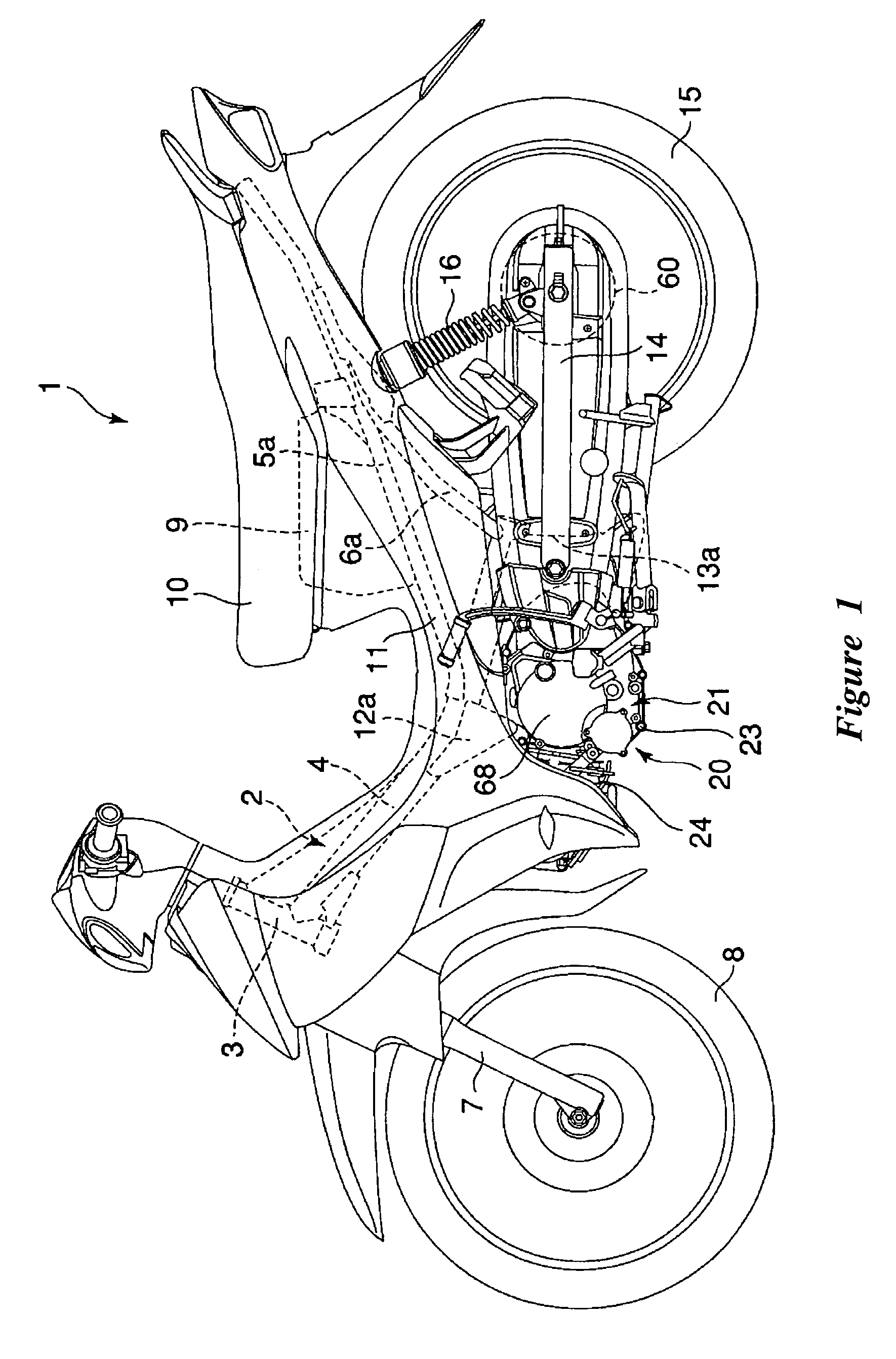
[0021] With reference now to FIG. 1, a motorcycle 1 is shown that comprises a backbone-type frame 2. The frame 2 comprises a steering head pipe 3, a main frame member 4 that extends rearward from the steering head pipe 3, right and left seat rails Sa, 5b that extend upward from the main frame member 4 and right and left seat pillar tubes 6a, 6b that extend upward from the main frame member 4 rearward of the right and left seat rails 5a, 5b.

[0022] The steering head pipe 3 is located at the forward end of the frame 2. The steering head pipe 3 supports a front wheel 8 via a front fork 7. The main frame member 4 defines the primary structure of the illustrated frame 2 and can be made, for example, of a steel pipe that has a generally circular cross-section. In some configurations, the main frame member 4 has other shapes, including, for instance but without limitation, a boxlike construction in cross section. The main frame member 4 can be formed by welding articles formed by press for...


PUM


Abstract

A motorcycle has a frame and a power unit. The frame comprises a main frame member extending rearward from a steering head pipe. The power unit comprises a drive source, power transmission devices attached to the output end of the drive source, and a casing that houses the power transmission devices and that is suspended from the main frame member. The casing of the power unit comprises a recess opening toward the main frame member. A boss is formed on the bottom of the recess and is suspended from the main frame member.

Description

CROSS-REFERENCE TO RELATED APPLICATIONS [0001] This application claims priority to Japanese Patent Application No. 2004-315,988, filed on Oct. 29, 2004, which is hereby incorporated by reference in its entirety. BACKGROUND OF THE INVENTION [0002] 1. Field of the Invention [0003] The present invention generally relates to a small motor vehicle with a power unit that comprises an engine and a belt-driven continuously variable transmission. More particularly, the present invention relates to a structure for mounting the power unit relative to a vehicle frame. [0004] 2. Description of the Related Art [0005] Small motor vehicles that are mainly used for commuting or for light-duty business purposes typically have a backbone-type frame. The frame generally comprises a steering head pipe that supports a front fork and a main frame member that extends rearward from the steering head pipe. [0006] The main frame member forms the primary structure of the frame. Brackets are secured to an inter...

Claims


Application Information

Patent Timeline
IPC IPC(8): B62M7/00B60K17/06B62J13/00B62K11/06B62M7/02B62M9/08B62M11/04B62M23/02F16H9/18F16H57/02F16H57/023F16H57/025F16H57/035
CPCB62K11/06B62K2202/00
Inventor ISHIDA, YOUSUKEOISHI, AKIFUMI
Owner YAMAHA MOTOR CO LTD
Why Eureka
Try Eureka