Methods for performing inspections and detecting chemical leaks using an infrared camera system

a camera system and infrared technology, applied in the field of visual detection and identifying chemical, gas and petroleum product leaks using an infrared camera system, can solve the problems of not being able to detect, and unable to find leaks using conventional methods

Inactive Publication Date: 2006-05-04
LEAK SURVEYS
View PDF59 Cites 138 Cited by
  • Summary
  • Abstract
  • Description
  • Claims
  • Application Information

AI Technical Summary

Problems solved by technology

One of the biggest challenges is trying to find the leaks using conventional methods.
Many conventional methods can simply miss a leak and not detect it if the detector is not properly positioned over or downwind of the leak.
Also, many conventional methods are very time consuming and labor intensive, which leads to more expense.
However, such systems require that the detector be within the stream or plume of the petroleum product leak.
They do not provide a visual image of the leak.
Also, these prior testing methods require the detector to be in the immediate proximity of the leak, which may be dangerous and / or difficult for the inspector.
Prior infrared systems designed for evaluating rocket fumes, for example, would provide an unfocused and fuzzy image, in which it was difficult to make out background objects.
For example, using an infrared camera that images a broad range of infrared wavelengths (e.g., 3-5 microns) typically will not be useful in detecting small leaks.
However, this system is not designed to provide a focused visual image to view the rocket exhaust.
Such systems have not been able to provide a focused image capable of quickly and easily detecting small leaks, nor being capable of detecting leaks from a distance (e.g., from a helicopter passing over a line).
However, with such systems, typically the narrow laser beam must cross the flow stream for the leak to be detected.
Hence, a leak may be missed if the laser beam does not cross the path of the leak and such systems often are unable to reliably find small leaks.
However, due to the lack of detection abilities and poor performance demonstrated by other prior and current systems, the EPA had not yet implemented such rules.

Method used


Image

  • Methods for performing inspections and detecting chemical leaks using an infrared camera system
  • Methods for performing inspections and detecting chemical leaks using an infrared camera system
  • Methods for performing inspections and detecting chemical leaks using an infrared camera system

Examples


Embodiment Construction

[0039] Referring now to the drawings, wherein like reference numbers are used herein to designate like or similar elements throughout the various views, illustrative embodiments of the present invention are shown and described. The figures are not necessarily drawn to scale, and in some instances the drawings have been exaggerated and / or simplified in places for illustrative purposes only. One of ordinary skill in the art will appreciate the many possible applications and variations of the present invention based on the following illustrative embodiments of the present invention.

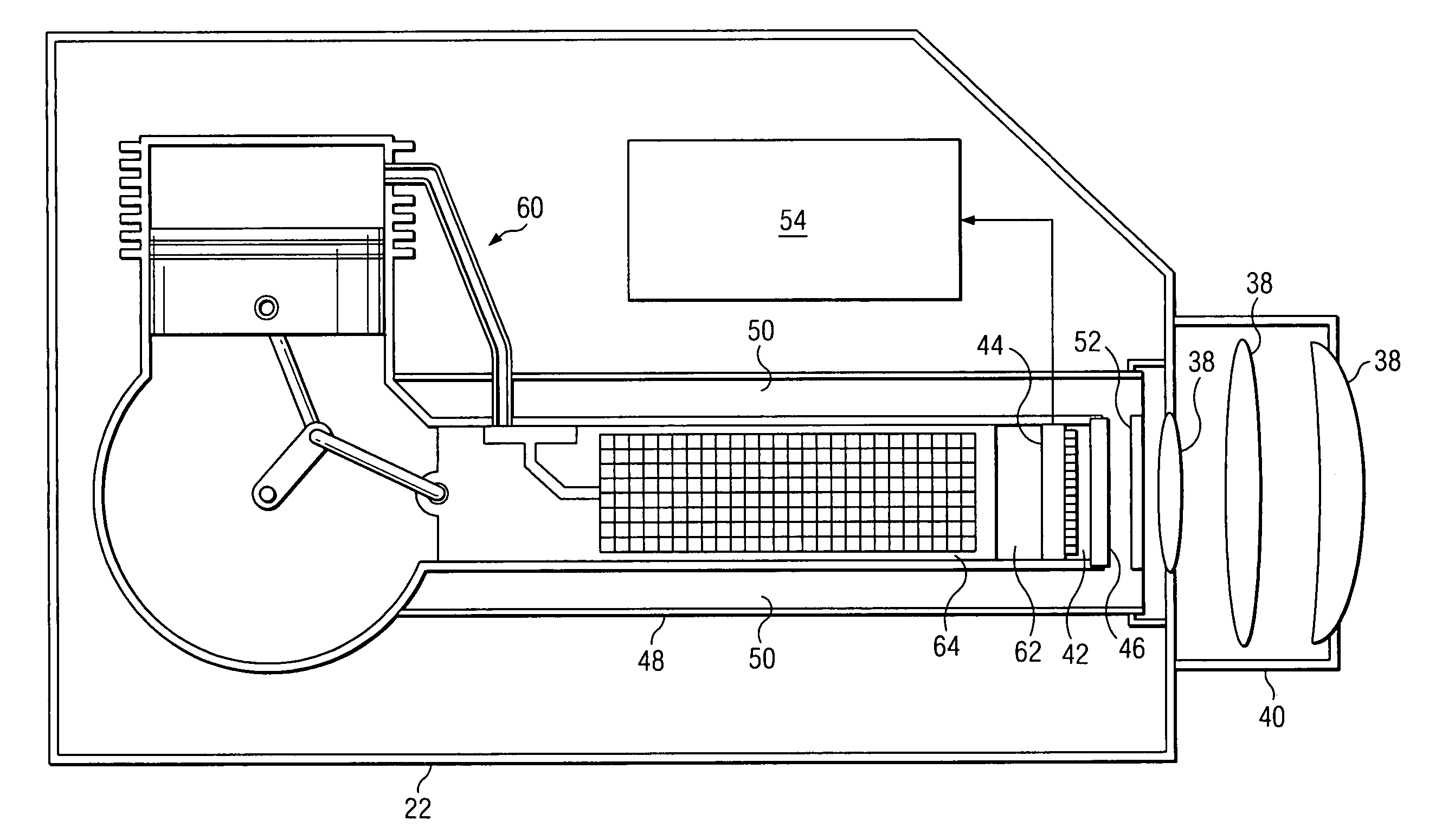
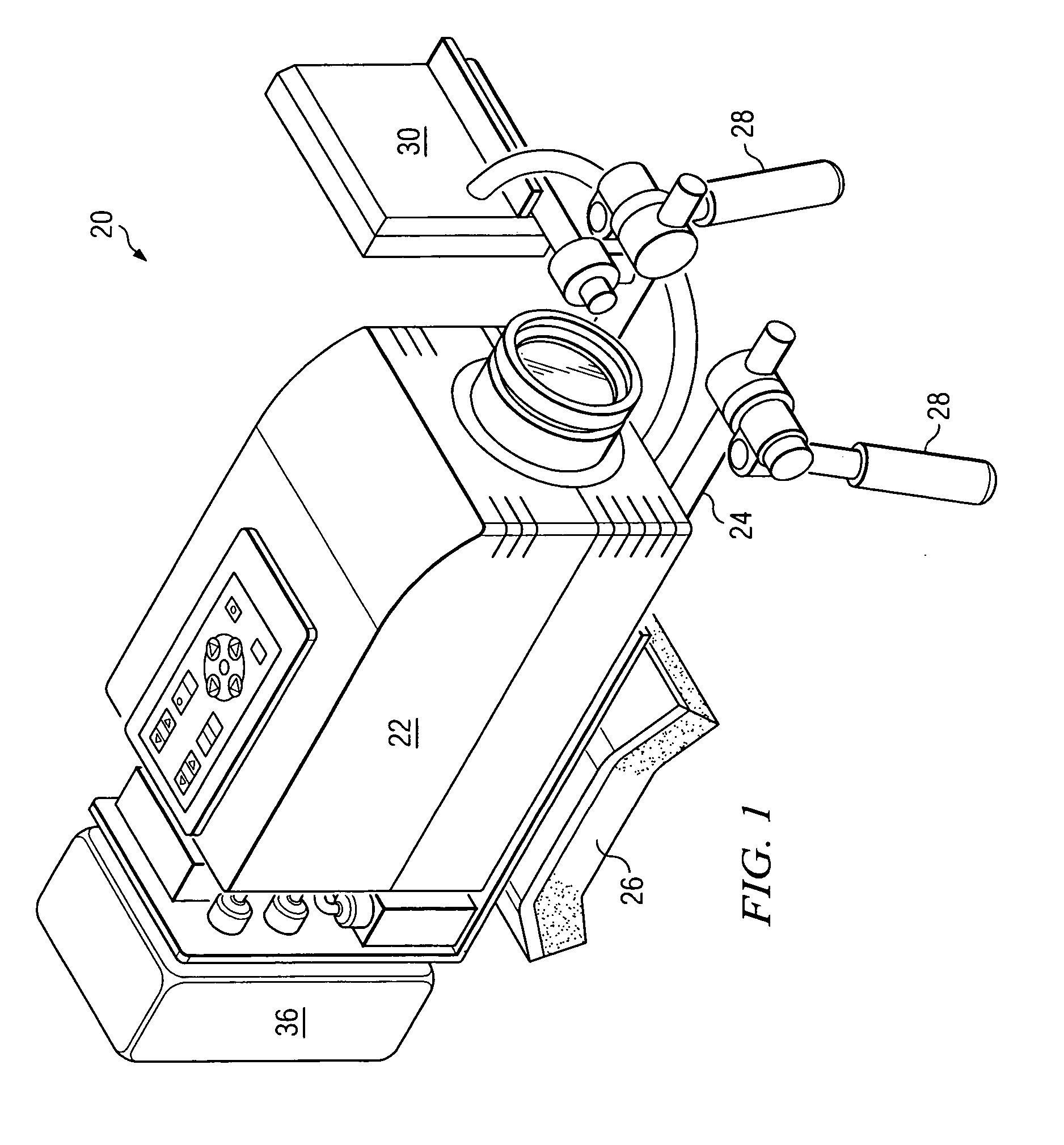
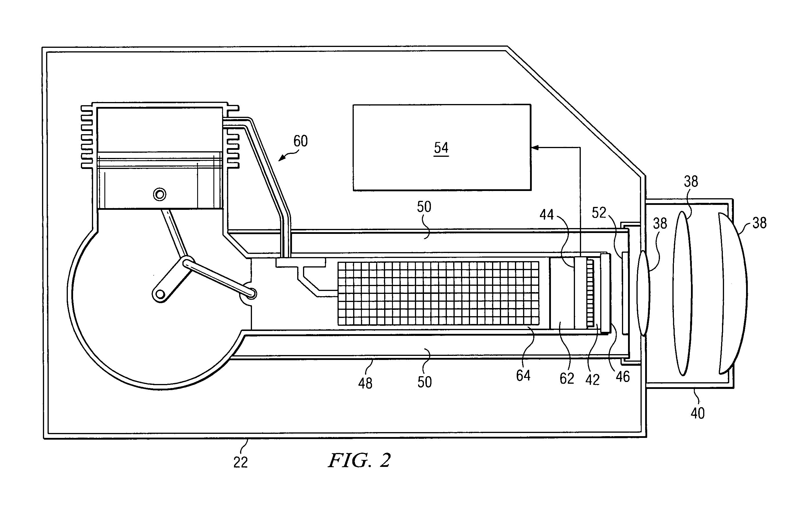
[0040]FIG. 1 shows a chemical leak inspection system 20 in accordance with a first embodiment of the present invention. The chemical leak inspection system 20 of the first embodiment includes a passive infrared camera system 22. The passive infrared camera system 22 of the first embodiment is adapted to provide a visible image representing a filtered infrared image of a chemical emanating (e.g., leaking) fr...


PUM

PropertyMeasurementUnit
temperatureaaaaaaaaaa
transmittanceaaaaaaaaaa
center wavelengthaaaaaaaaaa

Abstract

A method of visually detecting a leak of a chemical emanating from a component. The method includes: aiming a passive infrared camera system towards the component; filtering an infrared image with an optical bandpass filter, the infrared image being that of the leak; after the infrared image passes through the lens and optical bandpass filter, receiving the filtered infrared image with an infrared sensor device; electronically processing the filtered infrared image received by the infrared sensor device to provide a visible image representing the filtered infrared image; and visually identifying the leak based on the visible image. The passive infrared camera system includes: a lens; a refrigerated portion including therein the infrared sensor device and the optical bandpass filter (located along an optical path between the lens and the infrared sensor device). At least part of a pass band for the optical bandpass filter is within an absorption band for the chemical.

Description

[0001] This application is a continuation of PCT International Application No. PCT / 2004 / 012946, WO2005 / 001409 A2, filed on Apr. 26, 2004, entitled SYSTEMS AND METHODS FOR PERFORMING INSPECTIONS AND DETECTING CHEMICAL LEAKS USING AN INFRARED CAMERA SYSTEM, which claims the benefit of U.S. Provisional Application No. 60 / 477,994, filed on Jun. 11, 2003, entitled METHOD OF DETECTING GAS LEAKS USING AN INFRARED CAMERA SYSTEM, and U.S. Provisional Application No. 60 / 482,070, filed on Jun. 23, 2003, entitled METHOD OF DETECTING GAS LEAKS USING AN INFRARED CAMERA SYSTEM, and U.S. Provisional Application No. 60 / 540,679, filed on Jan. 30, 2004, entitled METHOD OF DETECTING GAS LEAKS USING AN INFRARED CAMERA SYSTEM, all of which application are hereby incorporated herein by reference. TECHNICAL FIELD [0002] The present invention relates generally to visually detecting and identifying chemical, gas, and petroleum product leaks using an infrared (IR) camera system. BACKGROUND [0003] In the oil a...

Claims


Application Information

Patent Timeline
Patent Type & Authority Applications(United States)
IPC IPC(8): G01J5/02G01J1/04G01J1/42G01J3/42G01J5/00G01J5/06G01MG01N21/35
CPCG01J1/0252G01J1/0488G01J1/4228G01J3/42G01J5/0265G01J5/061G01J5/0846G01J5/0862G01J2005/0077G01M3/202G01N21/3518G01N2021/1793G01N2021/3531H04N5/33G01N33/0036G01J5/0802G01M3/04
Inventor FURRY, DAVID W.
Owner LEAK SURVEYS
Why Eureka
Try Eureka