Stabilizer bushing

a stabilizer bushing and bushing technology, applied in the direction of twisting springs, mechanical equipment, transportation and packaging, etc., can solve the problems of significant equipment costs entailed by large scale equipment, insufficient bonding force or uneven bonding, and slippage can produce abnormal noise, etc., to achieve enhanced bonding stability

Inactive Publication Date: 2006-05-04
TOYOTA JIDOSHA KK
View PDF6 Cites 57 Cited by
  • Summary
  • Abstract
  • Description
  • Claims
  • Application Information

AI Technical Summary

Benefits of technology

[0033] The fifth mode teaches providing the gaps between circumferential opposite surfaces of the segmented parts at radially medial and outer portions of the inner rubber layer, while the radially inner most part of the inner rubber layer extends continuously over the entire circumference of the outer circumferential surface of the stabilizer bar via the adhesive. With this arrangement, when the inner rubber layer is subjected to compression

Problems solved by technology

A problem with this kind of stabilizer bushing 202 is that, due to input of twist or the like to the stabilizer bar 200, the inside face of the through-hole 216 can experience slippage relative to the stabilizer bar 200, and this slippage can produce abnormal noise, such as stick-slip noise.
However, this requires that vulcanization molding of the rubber elastic body 210 be carried out with the large, unwieldy stabilizer bar 200 set directly in the mold for the rubber elastic body 120, resulting in the problem of significant equipment costs entailed by large scale equipment.
As a result, appreciable necking K is produced at the two axial end portions and at the inner peripheral portion of the rubber elastic body 210, and the adhesive S which has been applied to the stabilizer bar 200 is caused to flow in the axial direction in association with deformation of the ru

Method used


Image

  • Stabilizer bushing
  • Stabilizer bushing
  • Stabilizer bushing

Examples


Embodiment Construction

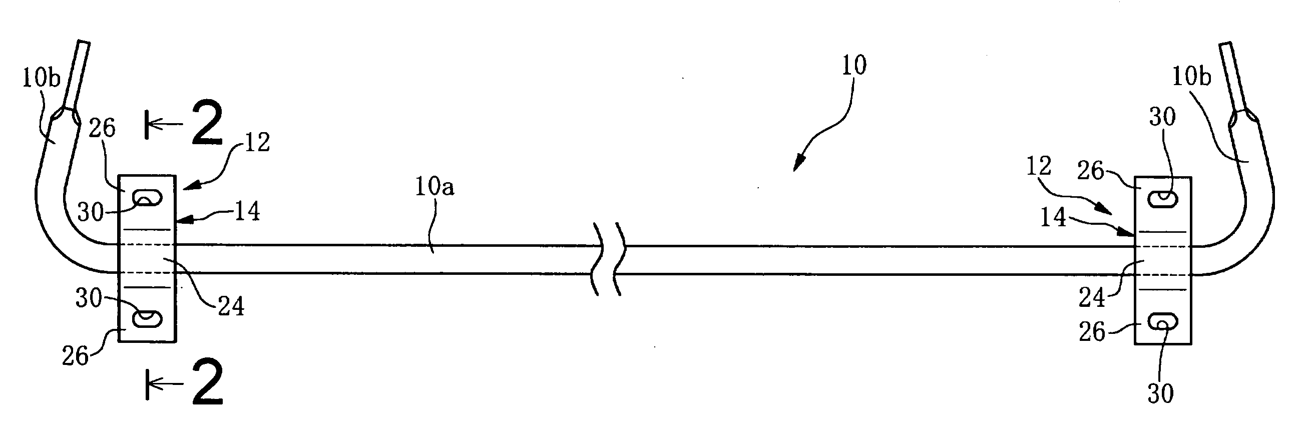
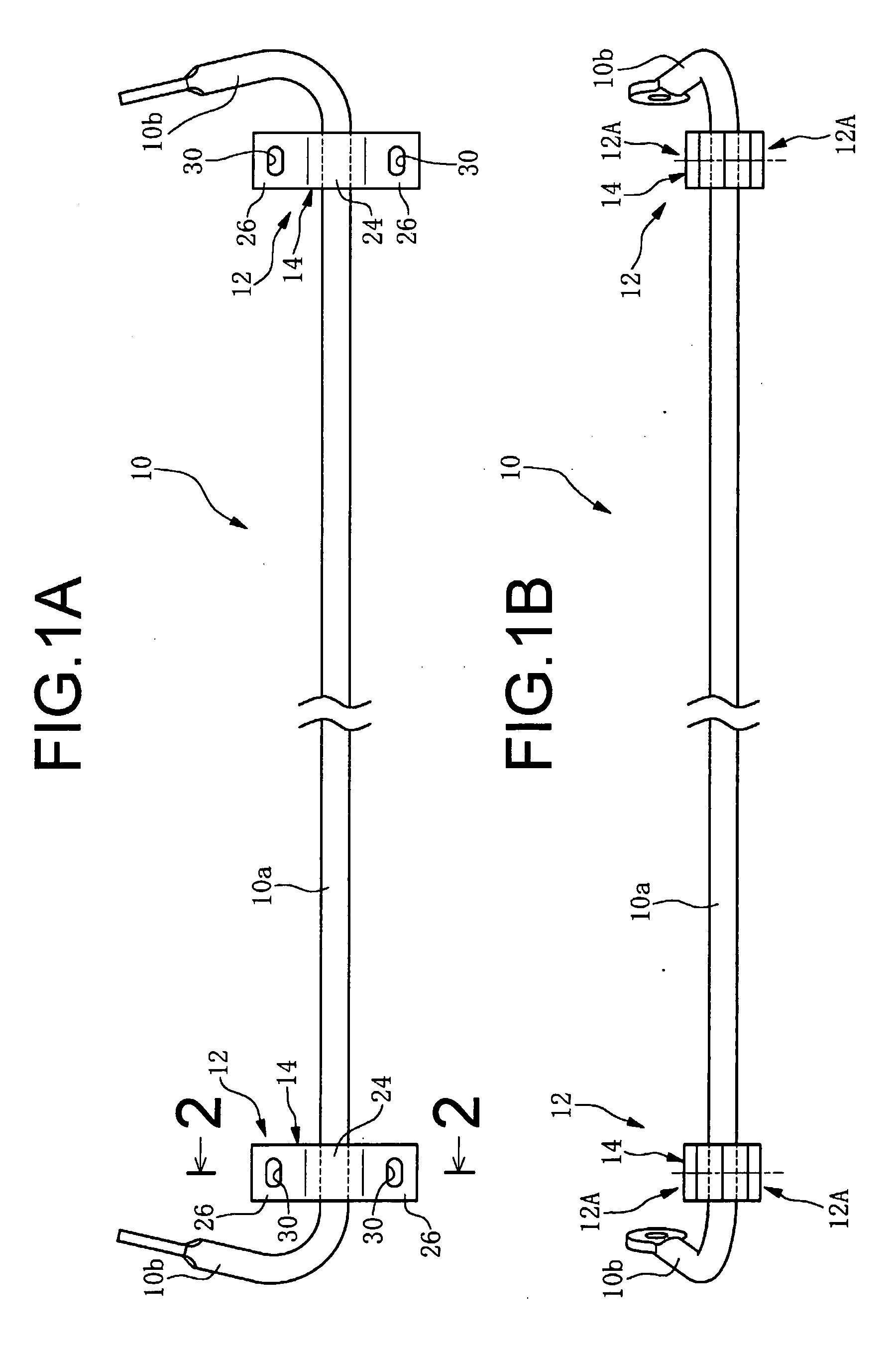
[0043] Referring first to FIGS. 1A and 1B, shown is a stabilizer bar 10 consisting of a metal rod, having a planar configuration overall that is generally a gate shaped, with its central section 10a. Namely, the stabilizer bar 10 is substantially linear in the vehicle width direction (lateral direction of the vehicle body), and is affixed to the vehicle body by stabilizer bushings 12 with arm sections 10b at its two ends affixed at their end portions to suspension arms that support wheels.

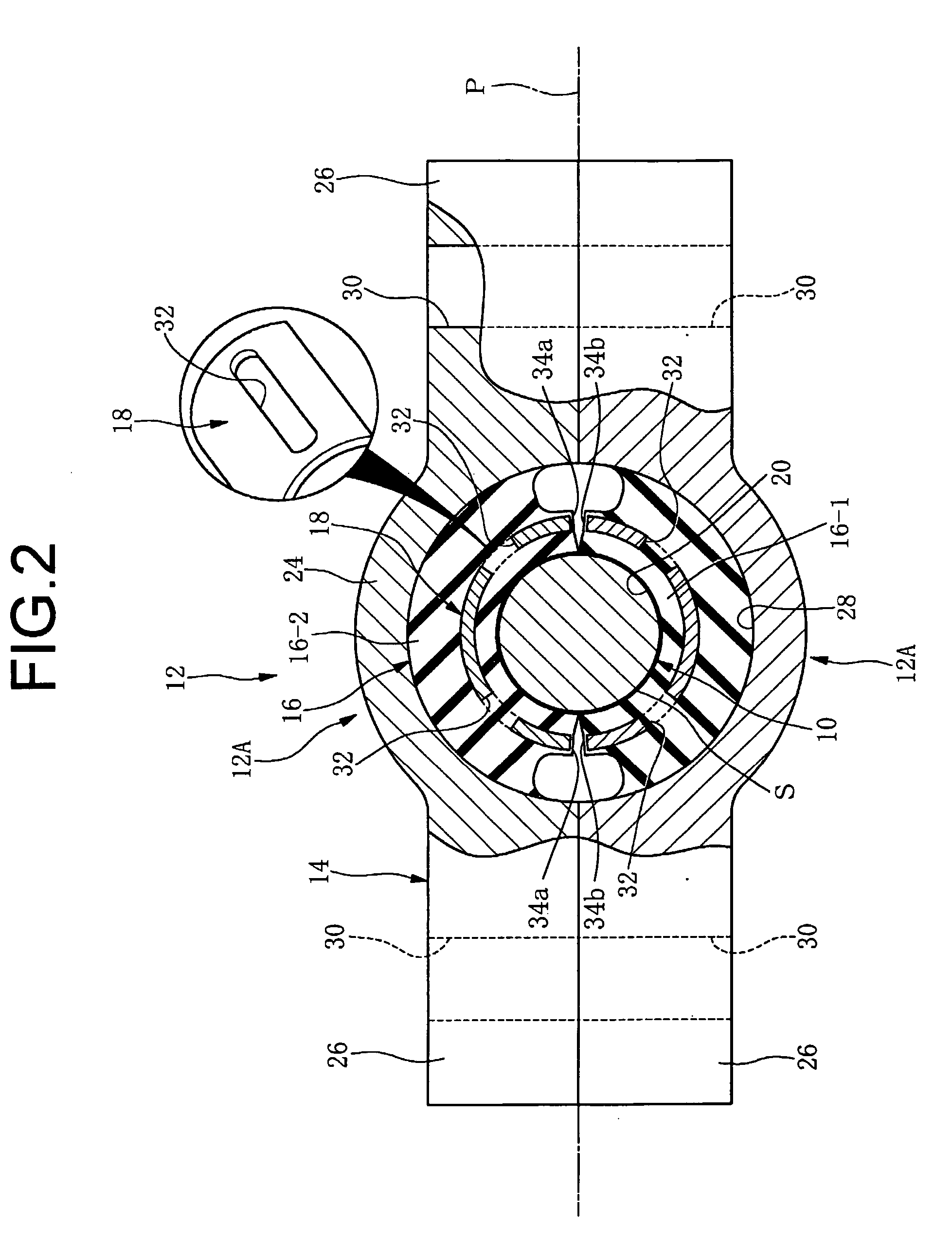
[0044] In FIG. 2 and FIG. 3, the specific arrangement of the stabilizer bushing 12 while attached to the stabilizer bar 10 is depicted in detail, together with the stabilizer bar 10 itself. As will be apparent from the drawings, the stabilizer bushing 12 of the embodiment has a rigid bracket 14 made of metal, a rubber elastic body 16, and a rigid medial plate 18 made of metal, embedded within the rubber elastic body 16.

[0045] The rubber elastic body 16 is of tubular shape in transverse cross sect...


PUM


Abstract

A stabilizer bushing including a rubber elastic body; a bracket and a medial plate embedded in a medial portion of the rubber elastic body in an axis-perpendicular direction so as to extend over substantially an entire axial length of the rubber elastic body so that the rubber elastic body is divided by the medial plate into an inner rubber layer and an outer rubber layer having a smaller spring constant than the inner rubber layer. The stabilizer bushing is composed of two circumferential segmented parts wherein the bracket and medial plate are integrally vulcanization bonded to the segmented parts, which segmented parts are assembled together sandwiching a stabilizer bar in the axis-perpendicular direction and subjected to compression in the axis-perpendicular direction so that an inside face of an through-hole is subjected to bonding to the outer circumferential surface of a stabilizer bar with an adhesive.

Description

INCORPORATED BY REFERENCE [0001] The disclosure of Japanese Patent Application No. 2004-316866 filed on Oct. 29, 2004 including the specification, drawings and abstract is incorporated herein by reference in its entirety. BACKGROUND OF THE INVENTION [0002] 1. Field of the Invention [0003] This invention relates to a stabilizer bushing for elastically supporting a stabilizer bar on a body of an automotive vehicle. [0004] 2. Description of the Related Art [0005] A stabilizer bar is a torsionally rigid spring (torsion bar) attached to the vehicle body in order to reduce tilting. The stabilizer bar is installed with the ends thereof mounted on the left and right suspension, and acts to suppress different vertical movements by the left and right wheels. For example, when turning a corner, when due to centrifugal force the outside suspension becomes compressed and the inside suspension becomes extended, as a result of which the body tends to tilt towards the outside due to the centrifugal...

Claims


Application Information

Patent Timeline
IPC IPC(8): B60G11/18
CPCB60G21/0551B60G2204/1222B60G2204/41B60G2206/8106B60G2206/821F16F1/371F16F1/3835
Inventor HAYASHI, YUKIOKOBAYASHI, KOICHI
Owner TOYOTA JIDOSHA KK
Why Eureka
Try Eureka