
Patch array feed for an automotive radar antenna

Active Publication Date: 2006-05-04
CONTINENTAL AUTOMOTIVE SYST INC
View PDF14 Cites 29 Cited by
  • Summary
  • Abstract
  • Description
  • Claims
  • Application Information

AI Technical Summary

Benefits of technology

[0011] The antenna of the transceiver assembly is preferably located at a focus of a parabolic surface of the dish, and is formed on a printed circuit board (PCB). The PCB can include a ground plane underneath the patches of the antenna, and can include additional circuitry necessary to operate the antenna. The antenna may be integral with the housing, formed on the housing, positioned within the housing, or at least partially exposed through the housing, so long as the loss of signal through any materials present on the assembly is minimized.
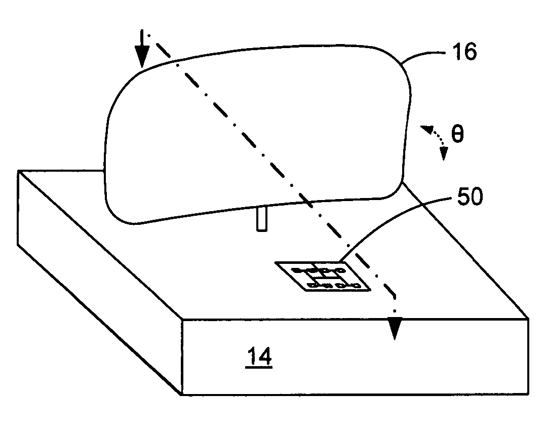
[0012] The patches of the antenna are preferably located at different positions on the antenna in a manner to preferentially steer the generated beam toward the dish, and are all connected to a common feed. By slightly altering the lengths of the feedlines to the patches, the phases of the various patches can be altered, with the overall effect being that the beam generated by the antenna can be generally steered toward the parabolic dish at an acute angle of incidence with respect to a plane of the patches.

Problems solved by technology

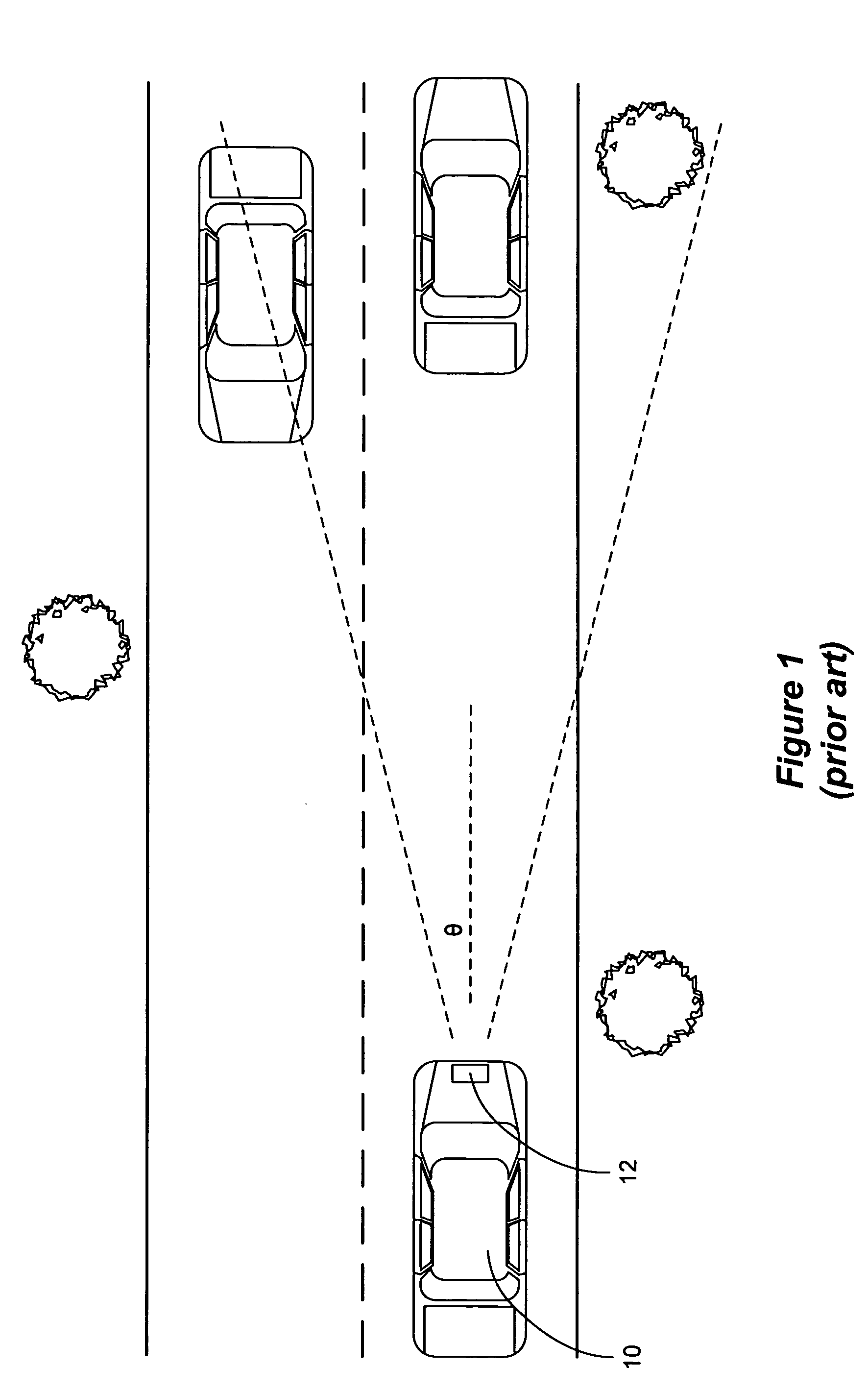
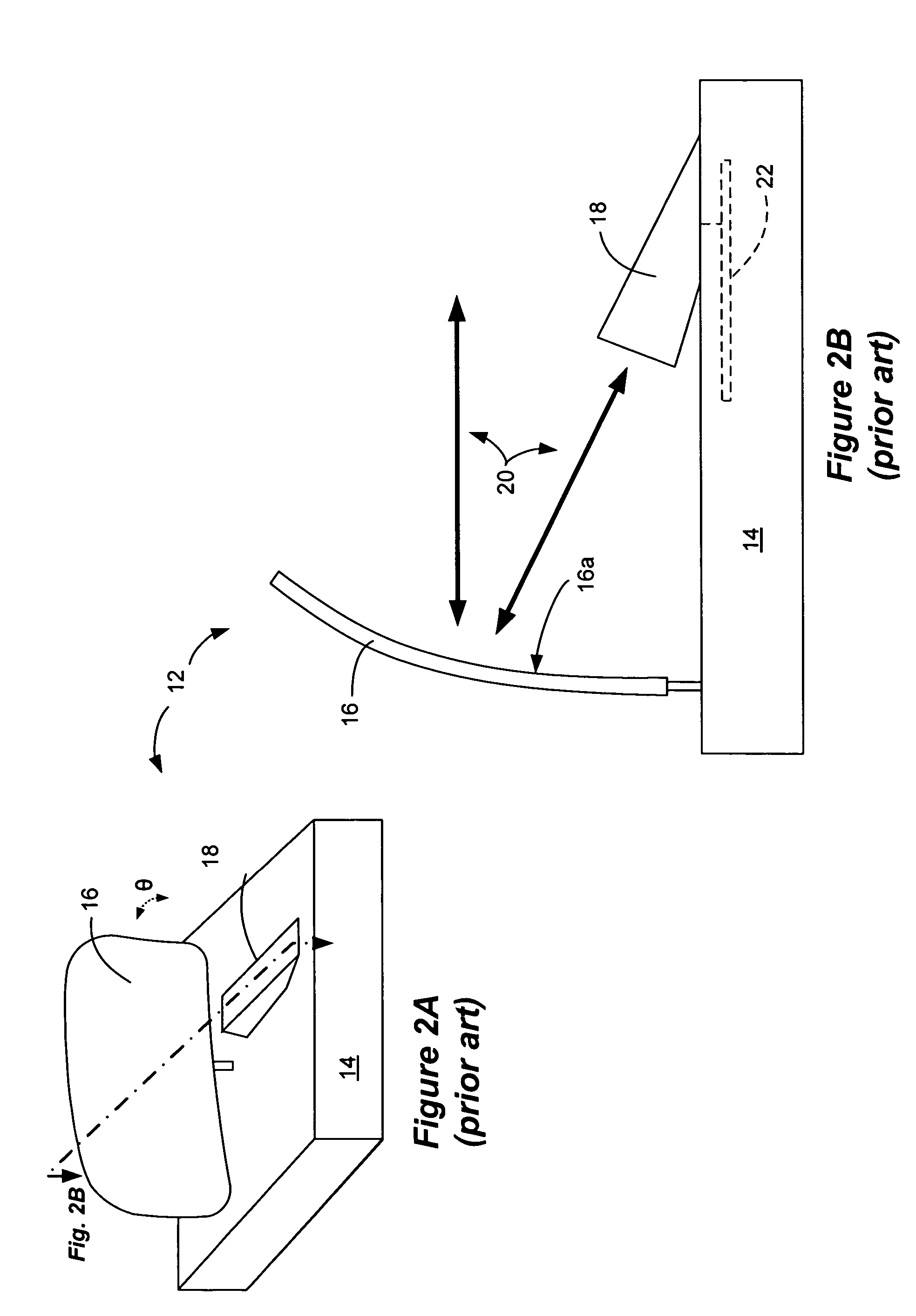
A major drawback to the collision detection transceiver 12 of the type illustrated is its cost, particularly as it related to the horn antenna 18.
This accordingly adds significant cost to the transceiver 12, which generally hampers use of the transceiver in vehicles that generally cannot be labored with substantial add-on costs.
Moreover, from a functional standpoint, the use of the horn antenna adds additional structural complexity to the overall design of the transceiver assembly, as it essentially “sticks out” of the assembly, must be precisely coupled to the PCB 22, is susceptible to damage and misalignment, etc.

Method used


Image

  • Patch array feed for an automotive radar antenna
  • Patch array feed for an automotive radar antenna
  • Patch array feed for an automotive radar antenna

Examples


Embodiment Construction

[0019]FIGS. 3A and 3B illustrate an embodiment of an improved vehicular collision detection transceiver 40 which employs a patch array feed antenna 50 in lieu of the horn antenna 18 used in prior designs (see FIGS. 2A & 2B). The patch feed antenna 50 works in a similar fashion to the horn antenna 18, i.e., it is capable of broadcasting and receiving radiation 20 and hence is useful in the context of the disclosed vehicular collision detection transceiver. However, the design of the transceiver is simplified, and is made significantly less expensive, through the use of the patch array feed antenna 50. As can be seen in FIG. 3B, and as will be made explained in further detail later, the patch array feed antenna 50 is preferably formed on the PCB (or more generically, “substrate”) 22 which includes the other circuitry needed for operation of the transceiver 40. Such additional and well-known circuitry includes the oscillators or resonators necessary to form the 77 GHz radiation, other ...


PUM


Abstract

An improved transceiver assembly for a vehicle for detecting potentially hazardous objects is disclosed. The transceiver assembly preferably comprises a patch array feed antenna having an array of a plurality of patches for generating a beam and for detecting the beam as reflected from the potential hazards. The antenna is formed in or on a housing which also contains a parabolic dish that moves to sweeps the beam of radiation towards the potential hazards outside of the vehicle. In a preferred embodiment, approximately 77 GHz radiation is generated from and detected by the antenna.

Description

CROSS REFERENCE TO RELATED APPLICATION [0001] This application is related to an application filed concurrently herewith, entitled “Tapered Slot Feed for an Automotive Radar Antenna,” attorney docket number IS01580AIC, which is incorporated herein by reference in its entirety. FIELD OF THE INVENTION [0002] This invention relates to an antenna structure having a patch array antenna feed in conjunction with a parabolic dish, particularly useful in a collision detection system in a vehicle. BACKGROUND [0003] Automotive technologies continually strive to make vehicles safer. In one aspect of vehicle safety, it is known to provide a vehicle with means to detect potential collisions and to take appropriate actions to avoid the same. For example, vehicles have been equipped with numerous types of sensors (e.g., infra-red sensors) which are able to broadcast radiation towards a potential obstacle (a tree, building, or another vehicle for example), receive radiation reflected from that obstac...

Claims


Application Information

Patent Timeline
IPC IPC(8): H01Q1/38
CPCH01Q1/3233H01Q1/42H01Q3/20H01Q3/245H01Q19/17H01Q3/46
Inventor FRANSON, STEVEN J.EMRICK, RUDY M.
Owner CONTINENTAL AUTOMOTIVE SYST INC
Learn More