Ink jet printer

a technology of jet printer and displacement sensor, which is applied in the direction of printing, other printing apparatus, etc., can solve the problems of increasing the inability to respond to the minute displacement of the printing position, and the increase in the manufacturing cost of the overall printer, so as to improve the light receiving efficiency of the light receiving device, and improve the detection accuracy of the displacement detection sensor

Inactive Publication Date: 2006-05-04
FUNAI ELECTRIC CO LTD
View PDF3 Cites 5 Cited by
  • Summary
  • Abstract
  • Description
  • Claims
  • Application Information

AI Technical Summary

Benefits of technology

[0010] In order to solve the above-mentioned problems, an object of the present invention is to provide an ink jet printer capable of improving detection accuracy of a displacement detection sensor while reducing manufacturing costs of the displacement detection sensor.
[0012] The displacement detection sensor has a light emitting device for emitting diffused light, a light receiving device for receiving the light emitted from the light emitting device and reflected by the recording paper sheet, converting the received light into an electric signal and outputting the electric signal to the displacement correction control means, a first lens for focusing the diffused light emitted from the light emitting device on the recording paper sheet and a second lens for focusing the light reflected by the recording paper sheet on the light receiving device. In the displacement detection sensor, the diffused light emitted from the light emitting device is focused by the first lens and reflected by the recording paper sheet, and then the diffused light is focused on the light receiving device by the second lens. In this manner, by making the amplitude of an electric signal output from the light receiving device larger, detection accuracy of the displacement detection sensor can be improved.
[0013] According to such a configuration, since the diffused light emitted from the light emitting device is focused by the first lens, the diameter of the beam spot projected on the recording paper sheet can be made smaller and the beam spot can be made brighter. Furthermore, since the light reflected by the recording paper sheet is focused on the light receiving device by the second lens, the light receiving efficiency of the light receiving device can be improved. Thereby, the amplitude of the electric signal output from the light receiving device can be made larger and the detection accuracy of the displacement detection sensor can be improved so as to adequately address high-resolution printing satisfactory to the user. Still furthermore, since the detection accuracy of the displacement detection sensor is improved by using inexpensive lenses instead of using the expensive light receiving device with a slit, manufacturing costs of the printer can be reduced. Still furthermore, since light is focused by the first lens and the second lens, the ratio of the light which reaches to the light receiving device against the light output from light emitting device becomes higher. Thus, the inexpensive low-powered light emitting device can be used, resulting in further cost reduction.

Problems solved by technology

Thus, the detection error of the displacement detection sensor 104 becomes large and therefore, minute displacement of printing position cannot be corrected to respond to high-resolution printing satisfactory to the user.
However, such a light receiving device having the slit used in the printer contributes to an increase in manufacturing costs of the overall printer due to its high cost price.
However, since a plurality of lenses must be integrally formed with a high degree of accuracy in both the displacement detection sensors, manufacturing costs become higher and thus, these sensors are not suited to printers for consumers requiring low price.
Furthermore, since the Fresnel lens disclosed in Japanese Laid-Open Patent Publication No. 2001-527472 diffuses light in the direction other than the displacement detection pattern, projection efficiency of the light to the recording paper sheet is deteriorated, thereby decreasing the S / N of the signal output from the light receiving device.

Method used


Image

  • Ink jet printer
  • Ink jet printer
  • Ink jet printer

Examples


Embodiment Construction

[0023] An ink jet printer in accordance with an embodiment of the present invention is described with reference to drawings.

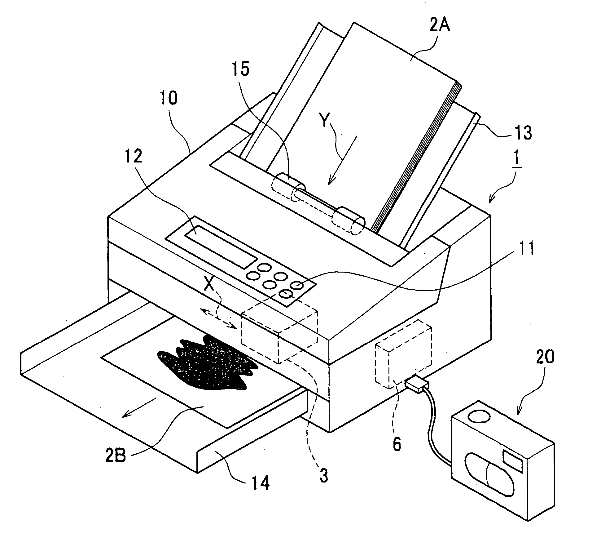
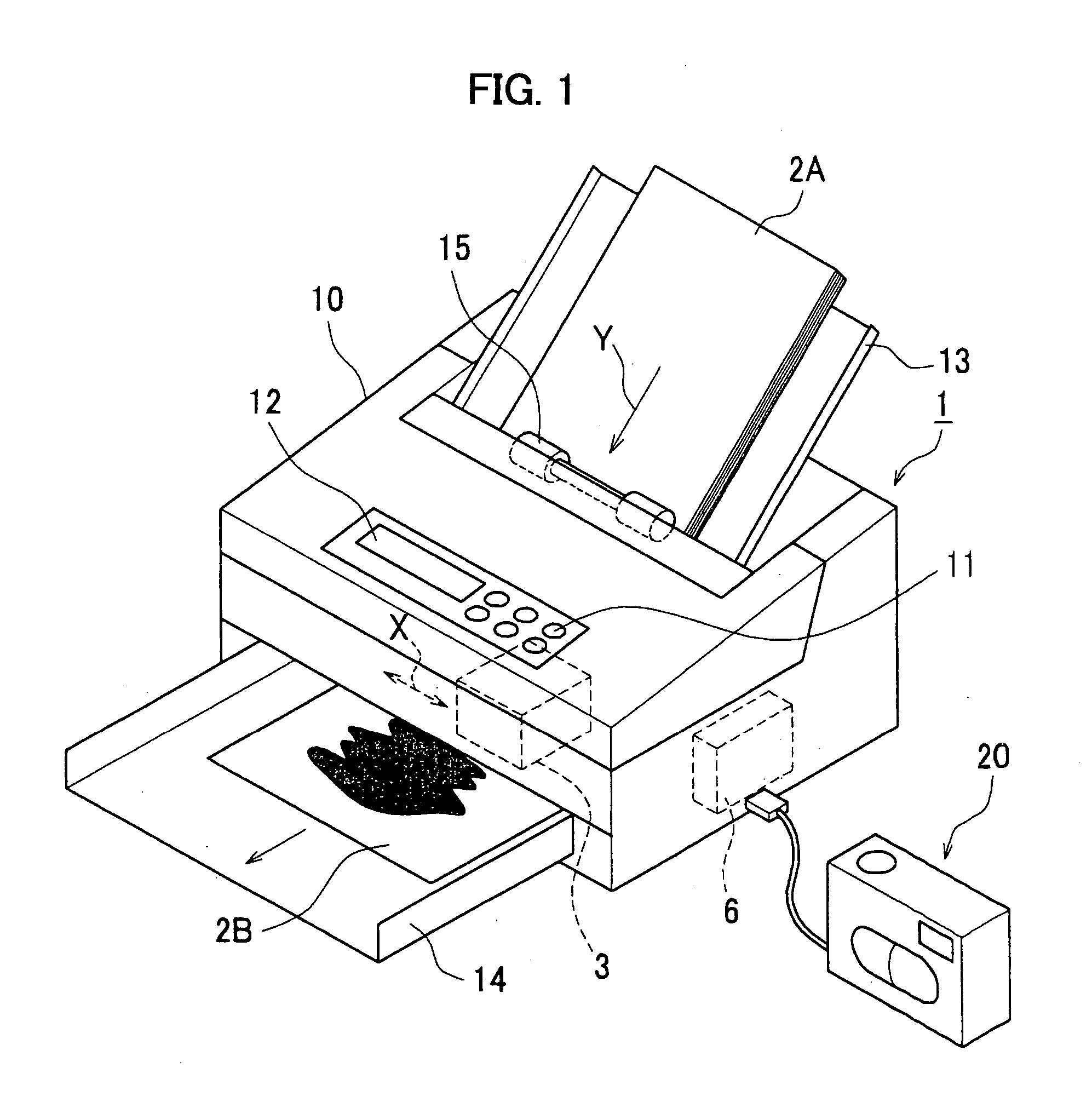
[0024]FIG. 1 shows a configuration of an ink jet printer 1. An operation switch 11 used for selecting a function among various functions of the ink jet printer 1 or inputting a print size, a number of sheets to be printed and so on, and a display device such as a liquid crystal display (LCD) for checking the selected function and input data and displaying an operation state of the ink jet printer 1 are provided on a top face of a housing 10 of the ink jet printer 1. A paper sheet feed tray 13 for holding recording paper sheets 2A to be printed is provided in an upper rear portion of the housing 10, and a paper sheet exit tray 14 for holding printed recording paper sheets 2B exit from the printer 1 is provided in a lower front portion of the housing 10.

[0025] A control circuit 6 for controlling entire of the ink jet printer 1 is provided in the housing 10. The...


PUM


Abstract

In an ink jet printer using an ink cartridge having an ink tank for storing ink therein and a recording head for ejecting the ink stored in the ink tank as ink drops and forming an image on a recording paper sheet, the detection accuracy of a displacement detection sensor for detecting a displacement of printing position is improved while reducing manufacturing costs of the displacement detection sensor. The displacement detection sensor is comprised of a light emitting device for emitting diffused light, a first lens for focusing the light emitted from the light emitting device on a recording paper sheet, a second lens for focusing the light reflected by the recording paper sheet and a light receiving device for receiving the light focused by the second lens. By focusing the diffused light emitted from the light emitting device by the first lens, the diameter of a beam spot projected on the recording paper sheet is made smaller than a longitudinal dimension and a width dimension of each component forming a displacement detection pattern.

Description

BACKGROUND OF THE INVENTION [0001] 1. Field of the Invention [0002] The present invention relates to an ink jet printer having a function of automatically correcting displacement of printing position occurring when an ink cartridge is mounted. [0003] 2. Description of the related Art [0004] Conventionally, an ink jet printer having a function of automatically correcting displacement of printing position by forming a predetermined displacement detection pattern on a recording paper sheet by a recording head after an ink cartridge is mounted, reading the pattern by a displacement detection sensor and adjusting control timing of the recording head on the basis of the result has become commercially practical. [0005]FIG. 6 shows a configuration of the displacement detection sensor for detecting the displacement of printing position used in the conventional ink jet printer. The displacement detection sensor 104 is comprised of a light emitting device 141 for emitting light on a recording ...

Claims


Application Information

Patent Timeline
Patent Type & Authority Applications(United States)
IPC IPC(8): B41J29/38
CPCB41J11/0095
Inventor SHOKI, MIKIOAOKI, RYUJINAKANISHI, TOSHIYUKIITOH, YUICHIROTSUJINISHI, MAKOTO
Owner FUNAI ELECTRIC CO LTD
Why Eureka
Try Eureka