Lighting source unit, illuminating apparatus using the same and display apparatus using the same

a technology of light source unit and illuminating apparatus, which is applied in the direction of lighting and heating apparatus, discharge tube luminescnet screen, instruments, etc., can solve the disadvantages of signal light in light utilization efficiency and thickness, the light output of a single light emitting diode, and the increase of mounting costs

Active Publication Date: 2006-05-04
PANASONIC LIQUID CRYSTAL DISPLAY CO LTD +1
View PDF5 Cites 38 Cited by
  • Summary
  • Abstract
  • Description
  • Claims
  • Application Information

AI Technical Summary

Problems solved by technology

However, since light output of a single light emitting diode is still insufficient in applications which require high light outputs, a plurality of light emitting diodes are arrayed to make up an illuminating apparatus.
1222-1225 (2004), each package must be again mounted on a printed circuit board by soldering or the like, thus causing an increased cost for the mounting, and a problem with regard to the reliability due to the double mounting, i.e., mounting of light emitting diodes in packages, and mounting of the packages on a printed circuit board.
However, when the signal light is used for illuminating a non-light emitting image display panel which needs a white illumination light source, the signal light is disadvantageous in the light utilization efficiency and thickness in order to mix red, green, and blue color light to generate white illuminating light, particularly when red, green, and blue light emitting diodes are used, because of the lack of color mixing means.

Method used


Image

  • Lighting source unit, illuminating apparatus using the same and display apparatus using the same
  • Lighting source unit, illuminating apparatus using the same and display apparatus using the same
  • Lighting source unit, illuminating apparatus using the same and display apparatus using the same

Examples


first embodiment

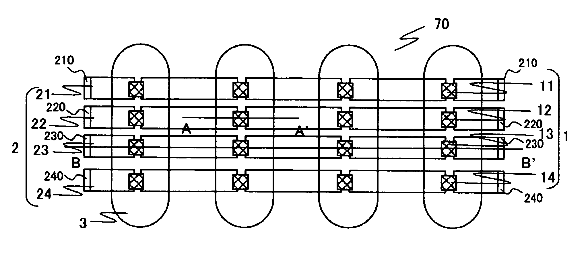
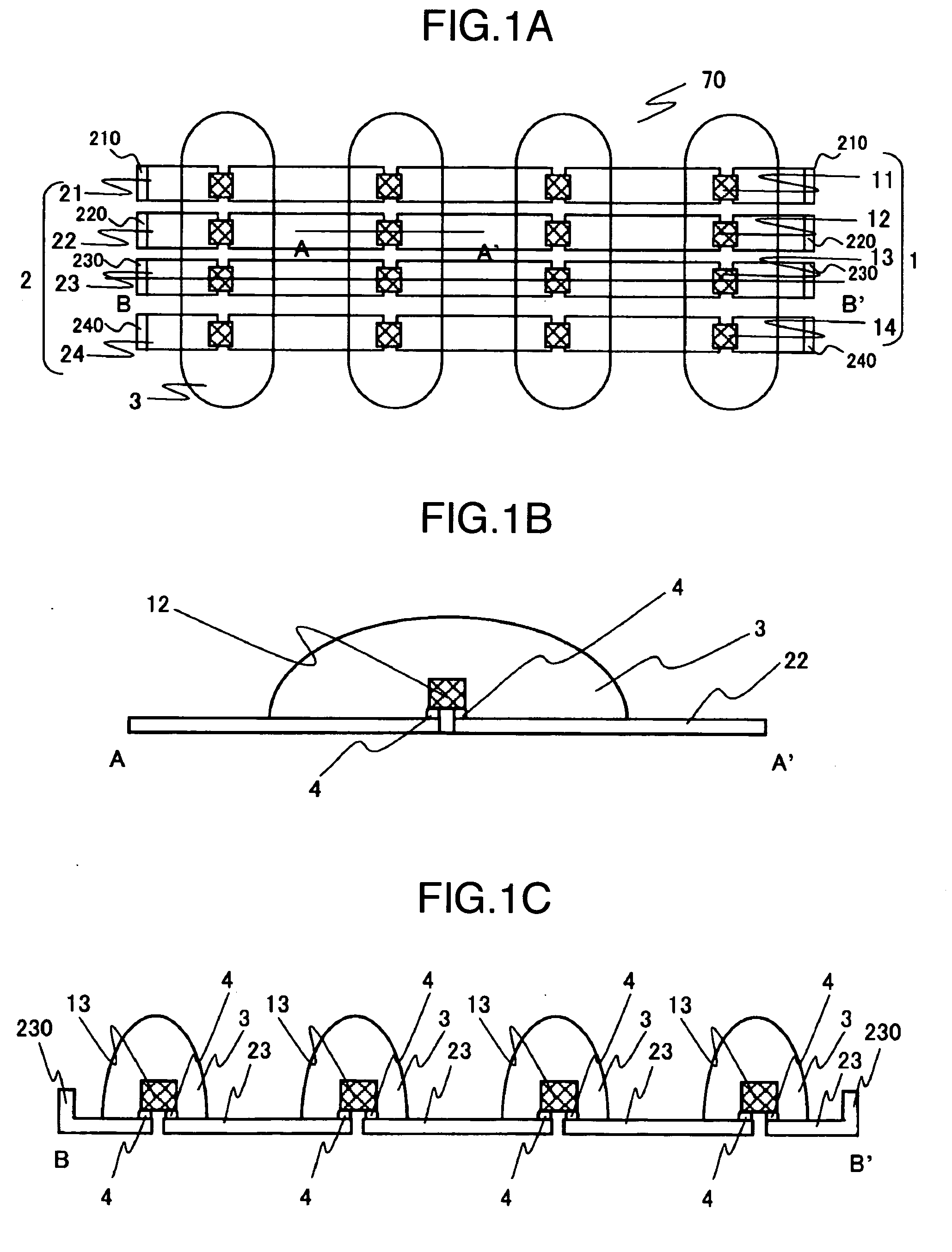
[0027]FIGS. 1A to 1C are diagrams for describing a light source unit 70 according to a first embodiment of the present invention, where FIG. 1A shows a top plan view of the light source unit; FIG. 1B shows a cross-sectional view taken along a line A-A′ in FIG. 1A; and FIG. 1C shows a cross-sectional view taken along a line B-B′ in FIG. 1A (along the longitudinal direction of a lead frame 23). The light source unit 70 comprises a plurality (four in FIG. 1A) of light emitting diode chips 1 (11-14); a plurality of sets (four sets in FIG. 1A) of lead frames 2 (21-24); and a transparent sealer 3.

[0028] Each of the lead frames 21-24 includes bends 210-240 at both ends thereof extending in a direction in which the light emitting diode chips emit light. The bends 210-240 have a function of positioning the associated lead frame to adjacent members when they are mounted in a display apparatus, a function of power supply terminals, and a function of facilitating mounting operations. Therefore...

second embodiment

[0047]FIGS. 4A, 4B are diagrams for describing a light source unit according to a second embodiment of the present invention, where FIG. 4A is a top plan view of the light source unit, and FIG. 4B is a cross-sectional view taken along a line B-B′ in FIG. 4A. The light source unit of the second embodiment comprises a reflecting mold in addition to the components of the first embodiment. The light source unit 70 of this embodiment can efficiently emit light radiated from the light emitting diode chips 1 in front by the action of the reflecting mold 7. Also, when the reflecting mold 7 is made of a diffuse reflective material, colored light from the respective light emitting diode chips 1 can be mixed in a desired manner.

[0048] The reflecting mold 7 may be implemented by a resin- or a ceramic-based mold, or a ring made of a variety of metals, the bottom of which is insulated. Further, a metal thin film may be formed on the surface of these materials to improve the reflectivity. A silve...

third embodiment

[0049]FIG. 5 is a diagram for describing a light source unit according to a third embodiment of the present invention, and corresponds to a cross-sectional view taken along the line B-B′ in FIG. 4A. A top plan view of the light source unit according to the third embodiment is similar to FIG. 4A. The light source unit 70 of the third embodiment increases the thickness of the lead frame 2 in an area on which the light emitting diode chip 1 is mounted. In this way, heat generated by the light emitting diode chip 1 can be effectively dissipated to the lead frame 2. This design of the lead frame 2 can be applied to the first embodiment to produce similar effects. In the third embodiment, the position at which the light emitting diode chip 1 is mounted is higher than the bottom surface of the reflecting mold 7, so that light is effectively directed to the reflecting mold 7 and therefore reflected to the top surface (opposite to the lead frame 2). Further, in consideration of a manufacturi...


PUM


Abstract

A thin light source unit employs a plurality of light emitting diode chips in multiple colors to generate highly uniform white light at a low cost and with a high light utilization efficiency. The light source unit has light emitting diode chips, lead frames, and a transparent sealer. A plurality of the light emitting diode chips in the same color are connected in series to three or more sets of the lead frames. The light emitting diode chips in at least three different colors are integrally sealed with the transparent sealer. An illuminating apparatus using the light source units, and a display apparatus using the illuminating apparatus are also provided.

Description

CROSS-REFERENCE TO RELATED APPLICATION [0001] The present application is related to U.S. patent application entitled “Illuminating Apparatus and Display Apparatus Using the Same” in the name of Toshiaki Tanaka, Hiroki Kaneko and Ikuo Hiyama, based on Japanese Patent Application No. 2004-320136 filed on Nov. 4, 2004, and U.S. patent application entitled “Illuminating Apparatus, Method for Fabricating the Same and Display Apparatus Using the Same” in the name of Hiroki Kaneko, Ikuo Hiyama, Toshiaki Tanaka, Masaya Adachi, Tsunenori Yamamoto and Haruo Akahoshi, based on Japanese Patent Application No. 2004-320409 filed on Nov. 4, 2004, and the contents of which are incorporated herein by reference.BACKGROUND OF THE INVENTION [0002] The present invention relates to a light source unit using light emitting diodes, an illuminating apparatus, and a display apparatus using this illuminating apparatus for illuminating a non-light emitting image display panel. [0003] An improved light emitting...

Claims


Application Information

Patent Timeline
Patent Type & Authority Applications(United States)
IPC IPC(8): F21V9/00H01L33/54F21V19/00F21Y101/02H01L33/56H01L33/62
CPCG02F1/133603G09F13/22H01L25/0753H01L2224/32245H01L2224/48091H01L2224/48247H01L2224/49107H01L2924/00014
Inventor HIYAMA, IKUOKANEKO, HIROKITANAKA, TOSHIAKIYAMAMOTO, TSUNENORIKONNO, AKITOYOKONDO, KATSUMIAKAHOSHI, HARUO
Owner PANASONIC LIQUID CRYSTAL DISPLAY CO LTD
Why Eureka
Try Eureka