Thin ply laminates

a technology of laminates and thin sheets, applied in the field of fiber composite materials, can solve the problems of limited realization of the full potential of critical in-plane loading carrying capacity, affecting the acceptance of composite materials for many applications, and affecting the performance of composite materials, etc., and achieves the effect of reducing the risk of delamination, and reducing the cost of the approach

Inactive Publication Date: 2006-05-04
ITOCHU CO LTD +3
View PDF13 Cites 39 Cited by
  • Summary
  • Abstract
  • Description
  • Claims
  • Application Information

AI Technical Summary

Benefits of technology

[0012] Using a known tow spreading process, conventional 12 k tows of carbon, glass or Kevlar fibers (approx. 0.12 mm thick) can be spread to form a ribbon as thin as 0.02 mm thick. With such thin plies, for example, a 3 ply orientation symmetric sublaminate according to the present invention can have the same 0.12 mm thickness as a conventional 0.12 mm ply. Minimum gauge is reduced to as low as one-sixth (⅙) of the thickness of co

Problems solved by technology

Regardless of its origin, delamination is a failure mode that often limits the realization of the full potential of the critical in-plane loading carrying capability of a multi-directional laminate.
Delamination is a serious threat to the acceptance of composites for many applications.
This approach is not only costly but also has dubious value.
Stitching causes additional damage to the composite laminate.

Method used


Image

  • Thin ply laminates
  • Thin ply laminates
  • Thin ply laminates

Examples


example 1

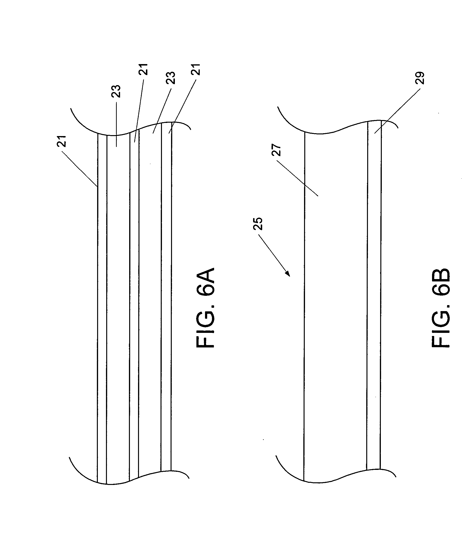
[0041] An example according to the present invention includes a combination of thick ply with 0.12 mm thickness and thin ply with 0.02 mm thickness. This is illustrated in FIG. 6A with thin plies 21 and thick plies 23. Further, a sublaminate 25 as in FIG. 6B can be a thick-thin hybrid having one thick [0] ply 27 and one thin [90] ply 29. The total thickness of this sublaminate module could be 0.12 mm+0.02 mm=0.14 mm and the percentage of [0] in this case would be 0.12 / 0.14=86 percent. Using this sublaminate to build a mast or boom provides a highly anisotropic structure having a toughness not possible with conventional laminates using only thick plies. For the latter case, the repeating module of thick plies would have to be 9 plies of [0] and one ply of [90]. The total sublaminate thickness would be 1.20 mm with the percentage of [0] equal to 90 percent. This design has 9 plies of [0] stacked together, which is a poor design from the standpoint of toughness. This practice makes mas...

example 2

[0042] If a higher percentage of [0] is desired, it is possible to have two thick plies [0] following by one thin ply [90]. In this case the percentage of [0] would be 0.24 / 0.26=92 percent. A tri-directional sublaminate module having two [0] and one [+ / −45] would have a percentage of [0] of 0.24 / 0.28=86 percent. Both these examples will give the mast or boom much tougher laminates. This hybrid structure is also useful for drive shafts, leaf springs, and sporting goods (e.g. pole vault shafts, hockey sticks, golf clubs, etc.).

example 3

[0043] Another example of a thick-thin ply laminate is a tri-directional sublaminate having one thick 0.12 mm ply [0] and two thin 0.02 mm, angled-plies [+ / −30] or [+ / −45], such as a [+30 / 0 / −30] or [+45 / 0 / −45] module. The total sublaminate thickness is 0.16 mm, which can be accomplished as one step in a ply drop. Tri-directional modules of any combination of thick and thin plies can be produced. This design flexibility allows products with significantly improved laminate performance and significant cost savings in manufacturing.


PUM

PropertyMeasurementUnit
Thicknessaaaaaaaaaa
Thicknessaaaaaaaaaa

Abstract

Fiber composite materials using thin plies with a thickness of less than 0.08 mm provide improved delamination resistance and thinner minimum gauge for laminates. Thin plies may be hybridized with conventional plies, interlaced for strength, and used with adhesives as reinforcement in bonding.

Description

CROSS-REFERENCE TO RELATED APPLICATIONS [0001] This application claims the benefit of U.S. Provisional Application Ser. No. 60 / 612,740 filed Sep. 24, 2004, and U.S. Provisional Application Ser. No. 60 / 668,341 filed Apr. 4, 2005.BACKGROUND OF THE INVENTION [0002] 1. Field of the Invention [0003] The present invention relates generally to fiber composite materials, and more particularly to composite materials using thin plies to achieve improved physical properties and the methods of manufacture of such materials. [0004] 2. Description of the Prior Art [0005] Conventional composite plies, with or without impregnated resin, are at least 0.12 mm thick. Laminates of composite plies are formed by stacking unidirectional plies together followed by some consolidation and curing process. Plies having different orientations are needed to provide mechanical properties in more than on direction. Thus, as a minimum two ply orientations are needed such as one ply oriented at a reference 0° angle ...

Claims


Application Information

Patent Timeline
IPC IPC(8): B32B7/02
CPCB29C70/088Y10T428/24975B29C70/22B29C70/885B32B3/12B32B5/024B32B5/06B32B5/10B32B5/12B32B5/26B32B7/02B32B7/12B32B15/00B32B15/14B32B15/20B32B2250/42B32B2262/106B32B2305/076B32B2307/54B32B2307/5825B32B2307/718B32B2419/00B32B2603/00B32B2605/18B29C70/202B31F1/07
Inventor TSAI, STEPHEN W.KAWABE, KAZUMASA
Owner ITOCHU CO LTD
Why Eureka
Try Eureka