
Dielectric loaded cavity filters for applications in proximity to the antenna

a cavity filter and dielectric technology, applied in the field of cavity filter, can solve the problems of high loss, poor filtering characteristics or good filtering characteristics, out-of-band interference signals producing additional noise in the system,

Inactive Publication Date: 2006-05-04
WESTELL
View PDF21 Cites 14 Cited by
  • Summary
  • Abstract
  • Description
  • Claims
  • Application Information

AI Technical Summary

Benefits of technology

[0014] It is an object of the invention to provide a high performance yet small-sized TMA / MHA / TMB that utilizes dielectric-based filters. The TMA / MHA / TMB is mounted close to the antenna to reduce insertion loss. The incorporation of dielectric resonators into the RF device provides high performance (e.g., low loss and excellent filtering capabilities) in a small size that is readily amenable for mounting close to the antenna—a location where size and weight is at a premium. Further features and advantages will become apparent upon review of the following drawings and description of the preferred embodiments.

Problems solved by technology

As mobile usage increases, wireless service providers are increasingly faced with the challenge of optimizing and / or expanding their wireless networks to provide better service for their customers while also minimizing their network capital expenditures.
Current TMAs or MHAs rely on air-filled, cavity-based filters which can have low loss but poor filtering characteristics or good filtering characteristics and high loss.
This is particularly important because the presence of out-of-band interfering signals will produce additional noise in the system because of harmonics generated within the non-linear components such as the LNA and mixers.
The problem is that in order to mount the LNA as close as possible to the antenna, the filter in the TMA or MHA must necessarily be small because of the limited space or “real estate” at the top of the tower.
In current air cavity-based filters, this necessitates poor filtering performance.
While high performance cavity filters are available, their large size and increased loss precludes them from being used in close-to-the antenna applications (e.g., in TMA or MHA systems).
Unfortunately, data is much less forgiving than voice with respect to errors.
The power amplifier design is much more complex and is limited by the out of the band emissions at maximum power.

Method used


Image

  • Dielectric loaded cavity filters for applications in proximity to the antenna
  • Dielectric loaded cavity filters for applications in proximity to the antenna
  • Dielectric loaded cavity filters for applications in proximity to the antenna

Examples


Embodiment Construction

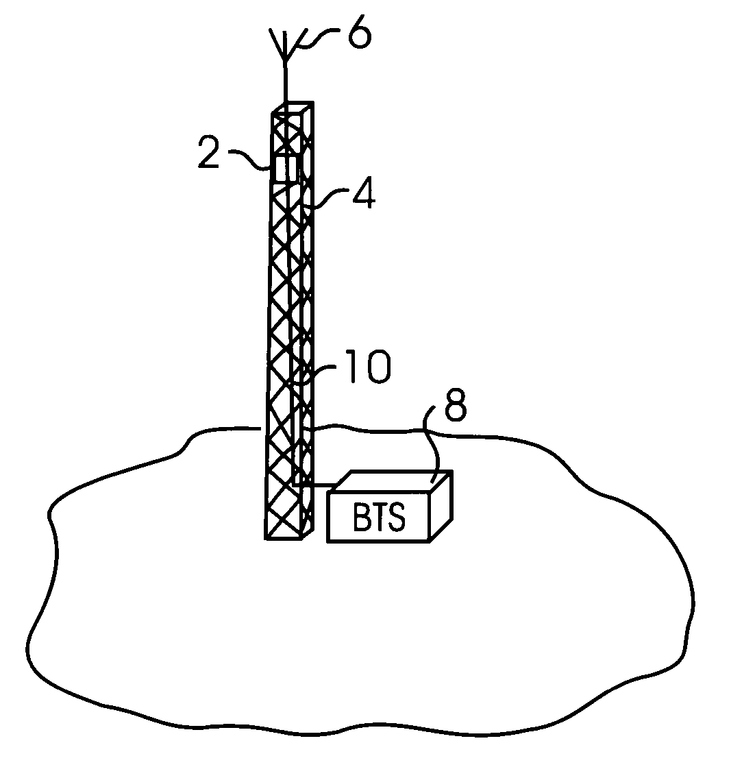
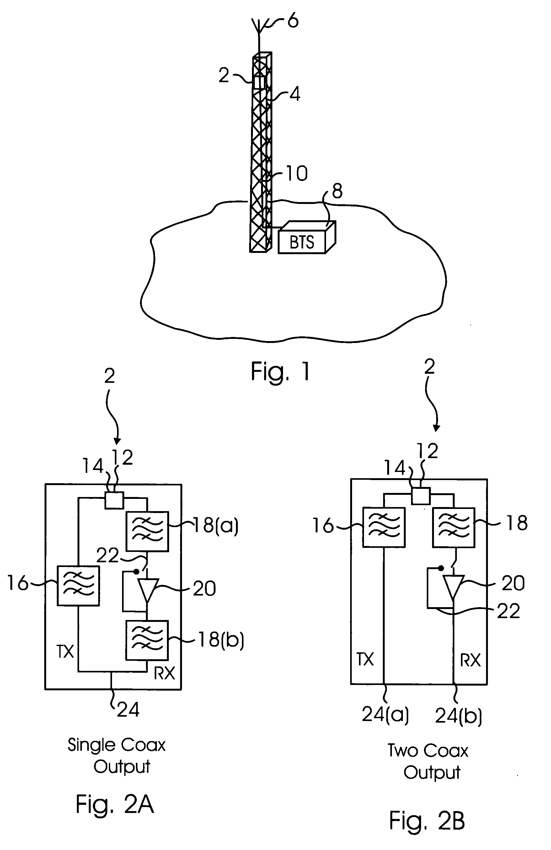
[0029]FIG. 1 illustrates a typical layout for an RF device 2 (e.g., TMA, MHA, TMB) (referred to herein as TMA). The TMA 2 is disposed on a tower 4 or other elevated structure adjacent to an antenna 6. The TMA 2 is coupled to the antenna 6 and a base station (BTS) 8 via coaxial cable 10. The TMA 2 may be powered by a separate power line (not shown) or, alternatively, the low noise amplifier (LNA) and any other electronics may be powered through current provided in the coaxial cable 10. In one aspect, the TMA 2 is located on the tower 4 within 10 feet of the antenna 6. In still other embodiments, the TMA 2 is located within 5 or even less than 3 feet of the antenna. The closer the TMA 2 is positioned adjacent to the antenna 6, the smaller the insertion loss created by the cabling connecting the TMA 2 to the antenna 6.

[0030] In another alternative aspect of the invention, the RF device 2 is integrally formed with the antenna 6. For example, the RF device 2 and antenna 6 may be include...


PUM


Abstract

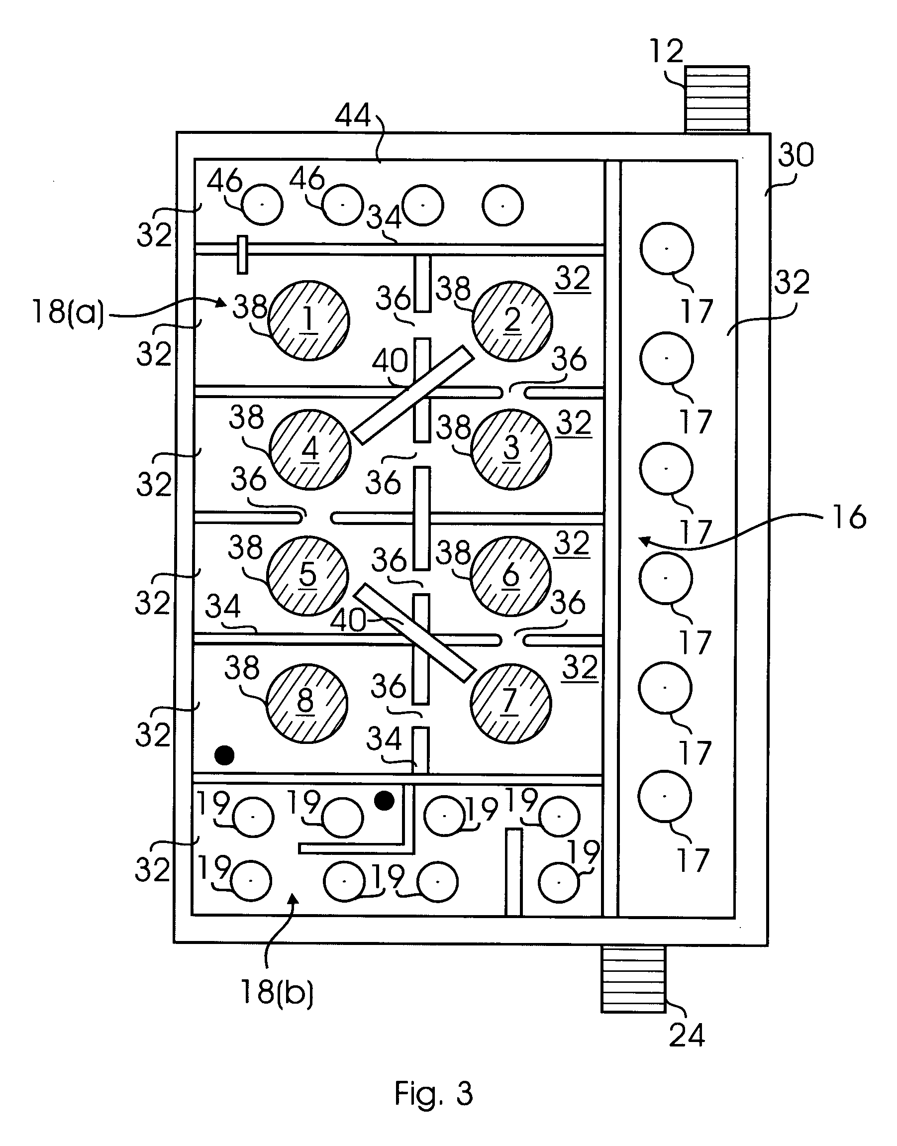
A dielectric-based RF device such as a tower mounted amplifier (TMA), mast-head amplifier (MHA), or Tower Mounted Boosters (TMB) includes a housing having a plurality of cavities and an input and an output, the input being coupled to the antenna and the output being coupled to a base station. The housing includes a transmission path with a transmit filter. The housing further includes a receive path with at least one receive filter and a low noise amplifier. The receive filter includes a plurality of cavities with a dielectric-based resonator disposed in at least some of the plurality of cavities. In one aspect, the RF device has a volume of less than about 155 in3. The RF device including the dielectric-based resonators has excellent out-of-band signal rejection with low loss. In addition, the RF device described herein is small enough to mount close to the antenna. The dielectric-based RF device has superior performance characteristics and a smaller footprint than conventional air cavity-based TMAs.

Description

RELATED APPLICATION [0001] This Application claims priority to U.S. Provisional Patent Application No. 60 / 623,552 filed on Oct. 29, 2004. The above-noted Application is incorporated by reference as if set forth fully herein. FIELD OF THE INVENTION [0002] The field of the invention generally relates to dielectric-based filters used in wireless applications. More specifically, the field of the invention relates to cavity-based dielectric filters that are mounted or otherwise located in close proximity to the antenna. Such filters have applications in Tower Mounted Amplifiers (“TMAs”) or Mast-Head Amplifiers (“MHAs”), Tower Mounted Boosters (“TMBs”) or any other application using dielectric filters close to the antenna such as, for example, remote RF applications, and repeater applications. BACKGROUND OF THE INVENTION [0003] As mobile usage increases, wireless service providers are increasingly faced with the challenge of optimizing and / or expanding their wireless networks to provide b...

Claims


Application Information

Patent Timeline
IPC IPC(8): H04M1/00
CPCH01P1/2086
Inventor EDDY, MICHAEL
Owner WESTELL
Learn More