Polyaxial bone screw

a bone screw and polymer technology, applied in the field of polymer bone screws, can solve the problems of difficult or impossible to do, need for a multitude of components that may loosen or even disassemble within the body, and most undesirable for components to be free to move around in the body. , to achieve the effect of convenient use, easy removal from the bone, and convenient us

Inactive Publication Date: 2006-05-04
JACKSON
View PDF61 Cites 116 Cited by
  • Summary
  • Abstract
  • Description
  • Claims
  • Application Information

AI Technical Summary

Benefits of technology

[0015] Therefore, it is an object of the present invention to overcome one or more of the problems with polyaxial bone screw assemblies described above. A further object of the invention is to provide apparatus and methods directed to a shank that uploads into a cavity in a head of the screw and that utilizes a retaining structure that is downloaded into the cavity. Another object of the invention is to provide a lightweight, low profile polyaxial bone screw that assembles in such a manner that the components cooperate to guard against disassembly after implantation. Another object of the invention is to provide bone screw components that do not require overly complicated fasteners or complicated methods of fastening within the bone screw head. Another object of the invention is to provide a polyaxial bone screw with features that present frictional or gripping surfaces for

Problems solved by technology

This is sometimes very difficult or impossible to do.
One undesirable attribute of some of the swivel-head implants is the need for a multitude of components that may loosen or even disassemble within the body.
It is most undesirable for c

Method used


Image

  • Polyaxial bone screw
  • Polyaxial bone screw
  • Polyaxial bone screw

Examples


Embodiment Construction

[0028] As required, detailed embodiments of the present invention are disclosed herein; however, it is to be understood that the disclosed embodiments are merely exemplary of the invention, which may be embodied in various forms. Therefore, specific structural and functional details disclosed herein are not to be interpreted as limiting, but merely as a basis for the claims and as a representative basis for teaching one skilled in the art to variously employ the present invention in virtually any appropriately detailed structure.

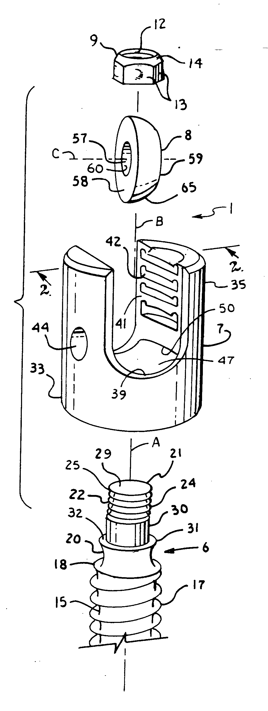
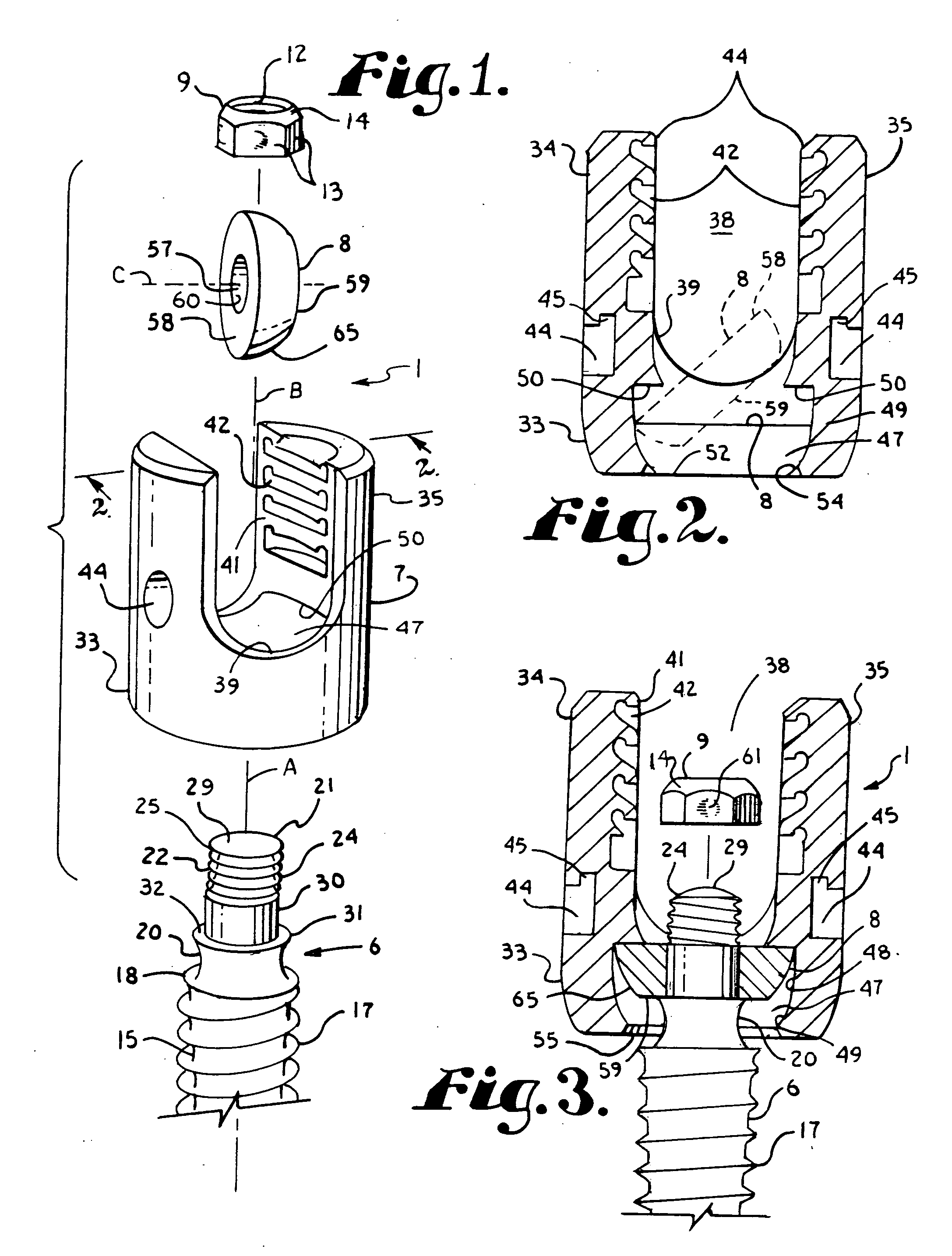
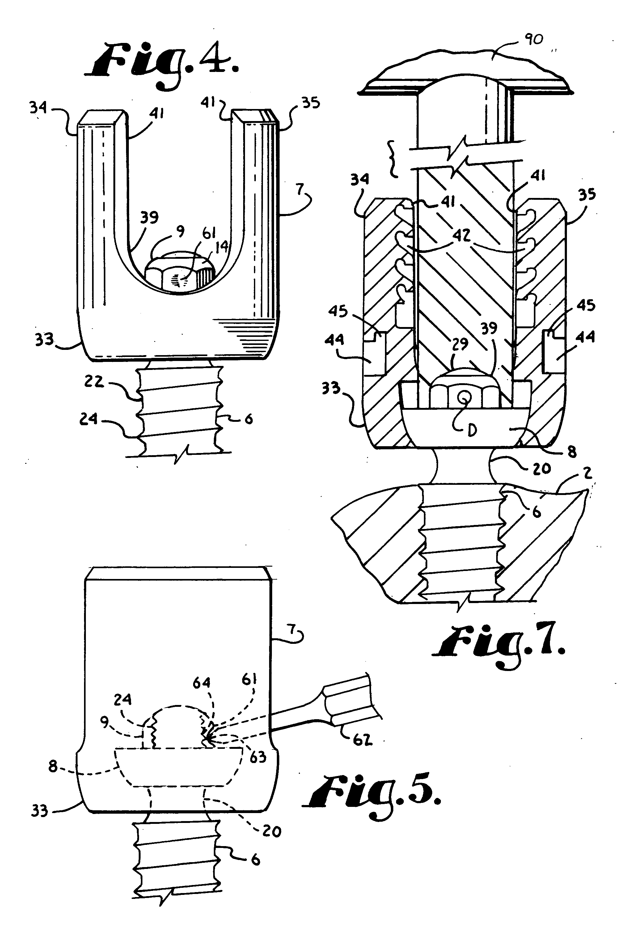
[0029] The reference numeral 1 generally represents a polyaxial bone screw apparatus or assembly according to the present invention, operably utilized by implantation into a vertebra 2 and in conjunction with a longitudinal member or rod 3 so as to secure the rod 3 in a fixed position relative to the vertebra 2.

[0030] With reference to FIGS. 1 and 8, the bone screw assembly 1 includes a shank 6, a head 7, a retaining structure or ring 8, a fastener or nut ...


PUM

PropertyMeasurementUnit
Angleaaaaaaaaaa
Structureaaaaaaaaaa
Deformation enthalpyaaaaaaaaaa

Abstract

A polyaxial bone screw assembly includes a threaded shank body having an upper capture structure, a head, a retaining ring and a nut. The external capture structure surface includes a threaded portion and a smooth portion; the smooth portion for slidably mating with the retaining ring and the threaded portion for rotatable attachment to the nut within a cavity of the head. The head has a U-shaped cradle defining a channel for receiving a spinal fixation rod. The head channel communicates with the cavity and further with a restrictive opening that allows for loading the capture structure into the head but prevents passage of the retaining ring out of the head. The retaining ring has an external substantially spherical surface that mates with an internal surface of the head, providing a ball joint, enabling the head to be disposed at an angle relative to the shank body. The nut fixes the retaining ring to the shank and also provides a tool engagement formation for driving the shank body into bone. The nut further includes a weakened area, providing for deformation and interlocking of threaded portions of the capture structure and the nut.

Description

BACKGROUND OF THE INVENTION [0001] The present invention is directed to polyaxial bone screws for use in bone surgery, particularly spinal surgery. Such screws have a head that can swivel about a shank of the bone screw, allowing the head to be positioned in any of a number of angular configurations relative to the shank. [0002] Many spinal surgery procedures require securing various implants to bone and especially to vertebrae along the spine. For example, elongate rods are often required that extend along the spine to provide support to vertebrae that have been damaged or weakened due to injury, disease or the like. Such rods are often supported by certain vertebrae and support other vertebrae. The most common mechanism for joining the rod to the spine is to implant bone screws into certain vertebrae which then in turn support the rod or are supported by the rod. Bone screws of this type may have a fixed head relative to a shank thereof. In the fixed bone screws, the head cannot b...

Claims


Application Information

Patent Timeline
IPC IPC(8): A61F2/30
CPCA61B17/7032A61B17/7037Y10T29/49826A61B17/704A61B2017/867
Inventor JACKSON
Owner JACKSON
Why Eureka
Try Eureka