Field circulatory constriction device

a technology of field circulatory and coiled tubes, which is applied in the field of tourniquets, can solve the problems of ineffective or reliable prior devices, lost blood in emergency situations, and inability to immediately help the injured person, and achieve the effect of preventing dirt and/or debris entry

Inactive Publication Date: 2006-05-04
SONOS MODELS
View PDF16 Cites 39 Cited by
  • Summary
  • Abstract
  • Description
  • Claims
  • Application Information

AI Technical Summary

Benefits of technology

[0007] A field circulatory constriction device in accordance with the present invention suitable for self application by an injured person in order to stop arterial blood flow or loss in an injured limb generally includes a strap, a latch for coupling the strap around a limb, and a buckle for cinching the coupled strap onto the limb. This mechanical action can be performed in a very brief period of time.
[0011] Still more particularly, the buckle in accordance with the present invention includes a hook for engaging the latch and the device preferably includes a sleeve for enclosing a block and tackle mechanism to prevent entry of dirt and / or debris.

Problems solved by technology

Loss of blood in emergency situations and particularly in military confrontations is a major cause of death.
In these situations, the injured person often does not have access to immediate medical assistance.
These prior devices have not proved to be effective or reliable.
However, such pneumatic tournament cuffs require a source of pressurized gas to inflate the bladder and infield sources of pressure such as hand pumps or bulbs are typically difficult to handle and may not provide a rapid enough response time in order to effectively stop arterial blood loss.

Method used


Image

  • Field circulatory constriction device
  • Field circulatory constriction device
  • Field circulatory constriction device

Examples


Embodiment Construction

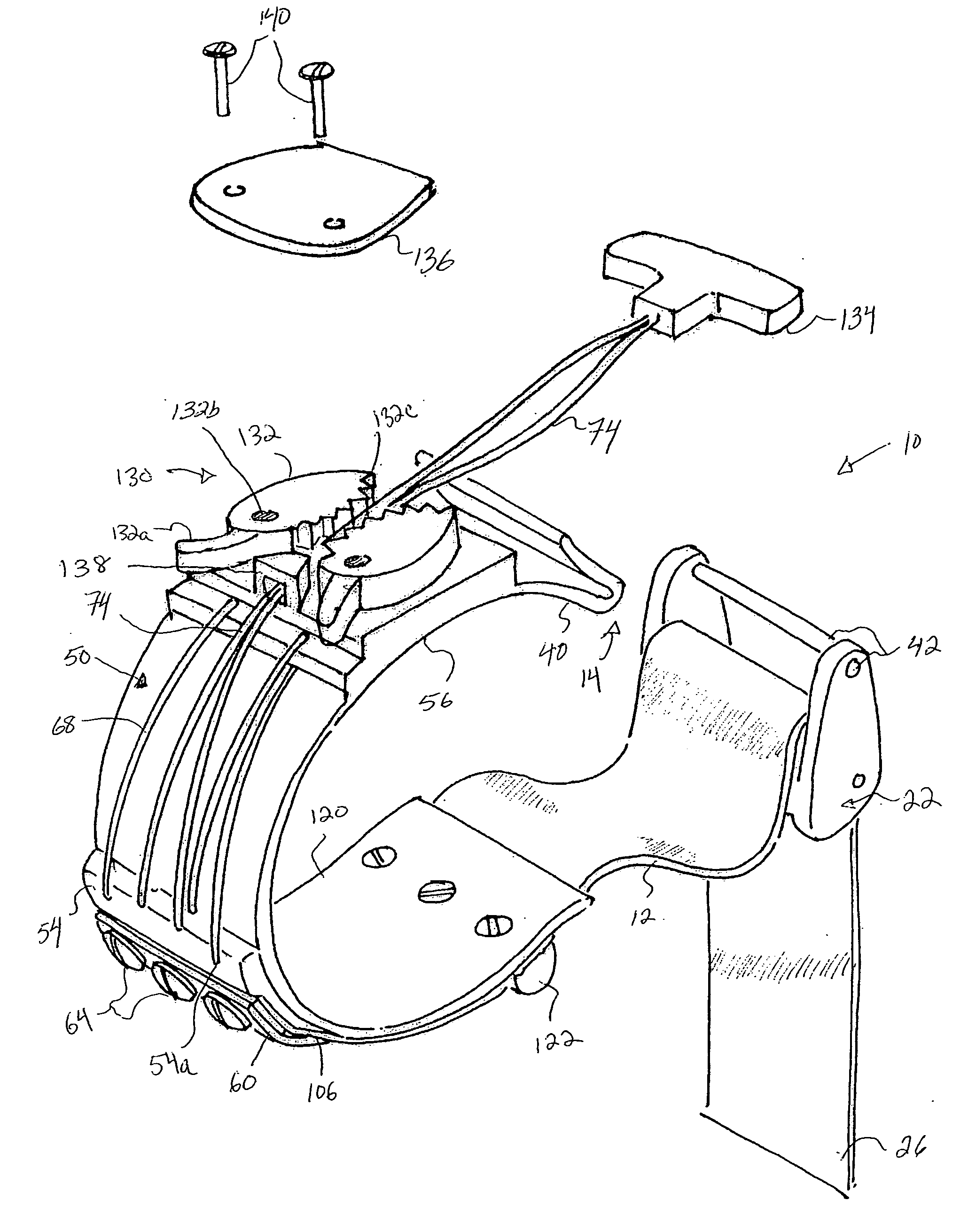
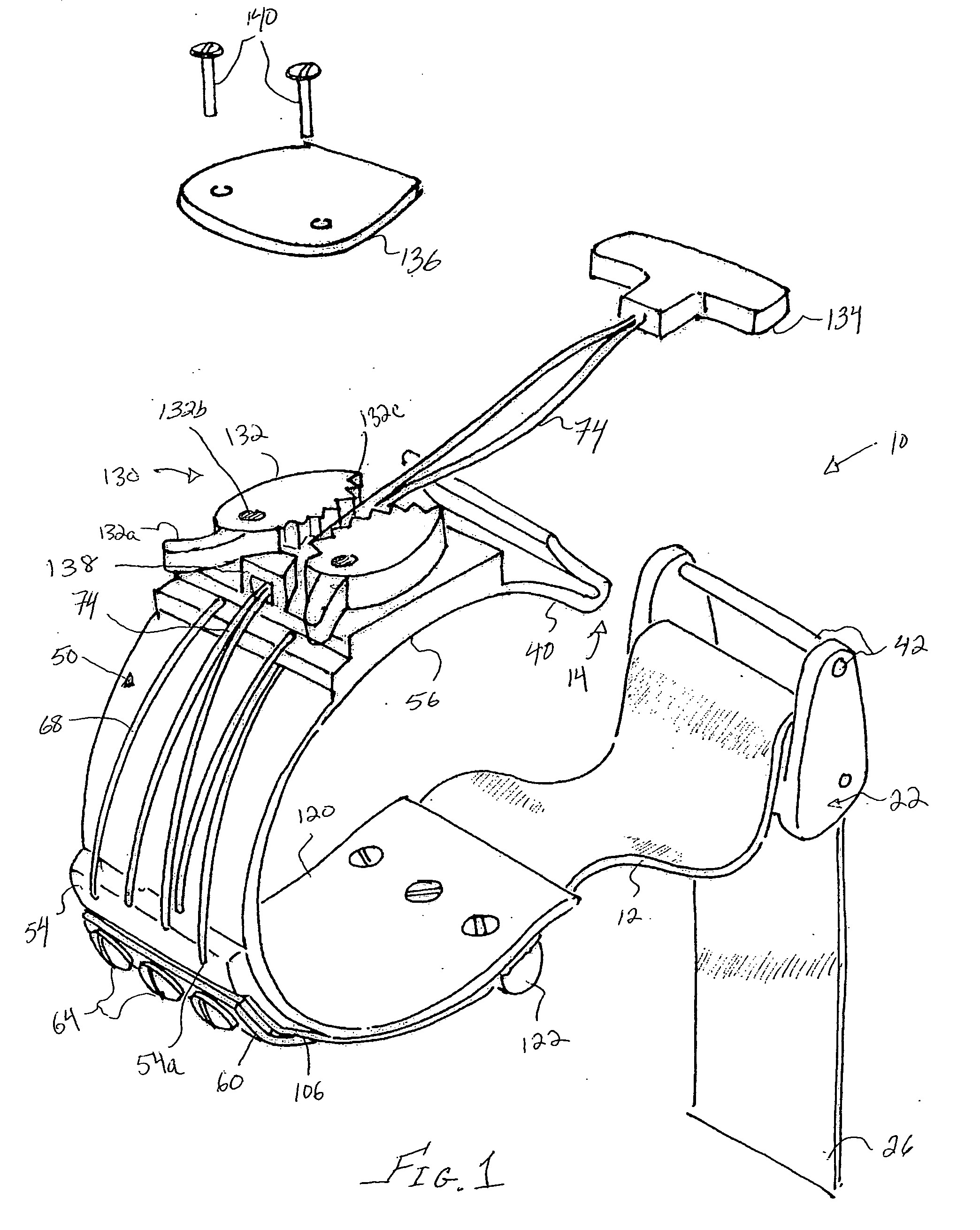
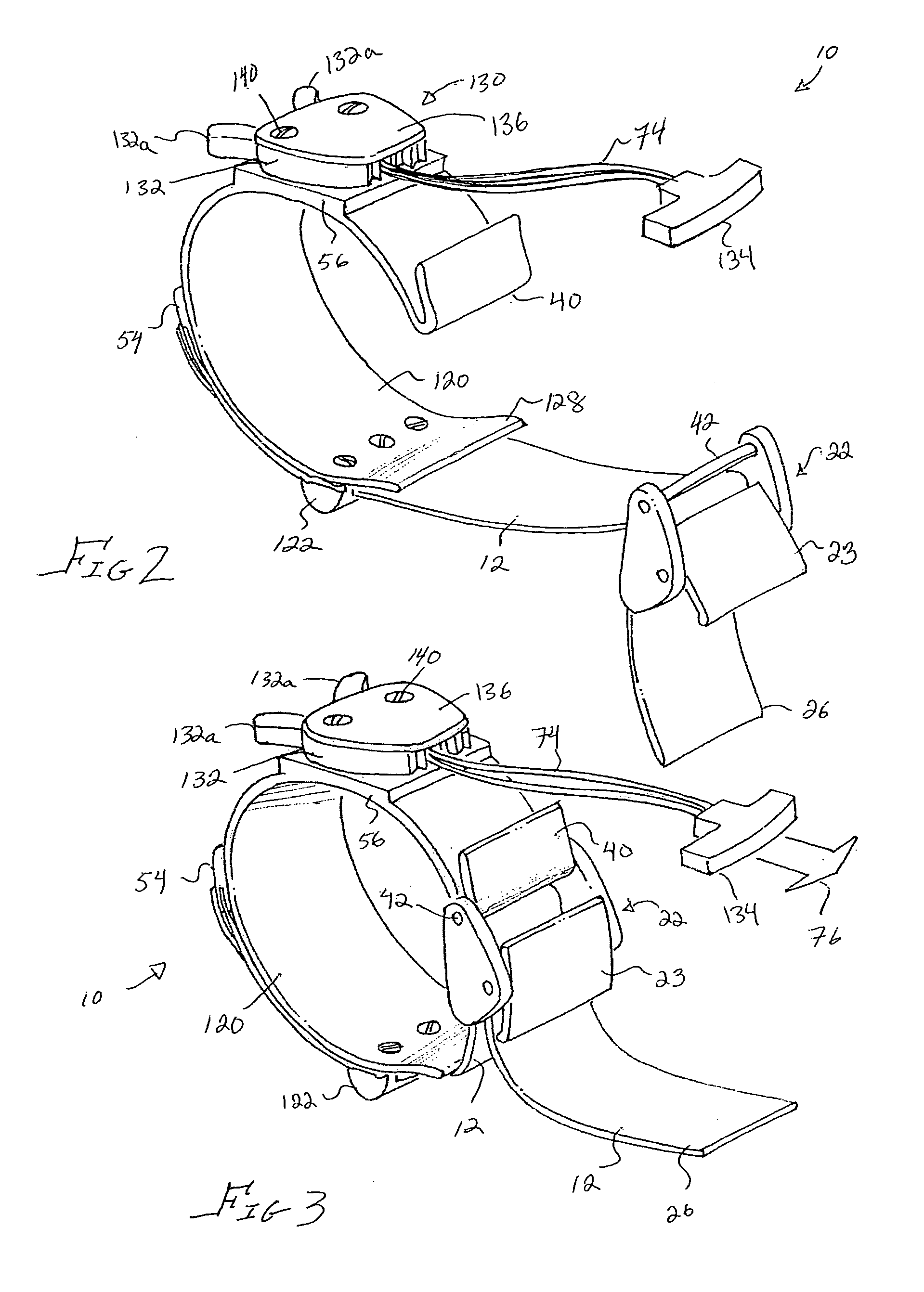
[0019] With reference to FIGS. 1-4, there is shown a field circulatory constriction device, or tourniquet, 10 in accordance with the present invention which is suitable for self-application by an injured person in order to stop arterial blood loss in an injured limb.

[0020] As shown, the device 10 generally includes a strap 12 made from any suitable flexible material and a hook 40 operable for coupling the strap 12 around a users limb such as, for example, an arm or a leg.

[0021] A buckle 22 is provided for cinching a coupled strap 12, see FIG. 3, by pulling on an end 26 of the strap 12. A locking head 30 of clamp 23 engages the strap 12 and forces the strap 12 against a backing plate 32. The angle of the locking head 30 in relation to the backing plate 32 allows the strap 12 to be pulled through the buckle 22 in one direction (e.g. away from the device 10) but not in the opposite direction unless the clamp is released. This arrangement prevents loosening of the strap 12 from around...


PUM


Abstract

A field circulatory constriction device suitable for self-application by an injured person in order to stop arterial blood loss in an injured limb includes a strap and a latch for coupling the strap around the limb. A buckle is provided for cinching the coupled strap to the limb and a block and tackle mechanism is provided for increasing the pressure of the cinch strap onto the limb.

Description

BACKGROUND OF THE INVENTION [0001] The present invention is generally directed to a tourniquet for stopping blood loss from an injured limb and is more particularly directed to a tourniquet for use in emergency situations in which a user is able to apply the tourniquet to his or her own arm or leg and occlude blood flow with the use of a single hand. [0002] Loss of blood in emergency situations and particularly in military confrontations is a major cause of death. In these situations, the injured person often does not have access to immediate medical assistance. It is also well known that the use of a tourniquet to stop blood loss provides temporary first aid treatment until medical assistance is available. [0003] It should be quite apparent that in these situations time is of the essence and thus one handed simple and expedient operation of such an infield circulatory constriction device must be efficiently effected. [0004] Many attempts have been made to develop tourniquets for su...

Claims


Application Information

Patent Timeline
Patent Type & Authority Applications(United States)
IPC IPC(8): A61B17/00
CPCA61B17/1322A61B17/1327
Inventor TENBRINK, CARLSTOCKS, DAVIDFRINK, TIM
Owner SONOS MODELS
Why Eureka
Try Eureka