Pigtail spring contacts for implanted medical devices

a medical device and spring contact technology, applied in the field of implantable medical devices, can solve the problems of large surgical operation with attendant risk factor, large number of discrete electrical impulses, and very undesirable setscrews

Active Publication Date: 2006-05-04
BAL SEAL ENG CO INC
View PDF2 Cites 13 Cited by
  • Summary
  • Abstract
  • Description
  • Claims
  • Application Information

AI Technical Summary

Problems solved by technology

Once the leads are implanted in the body, removal may involve major surgery with an attendant risk factor.
While some applications are very simple requiring only two leads because they only have to transmit two discrete signals to the tissues, others are very complex and require a very large number of discrete electrical impulses.
Setscrews are very undesirable where large numbers of connectors are required because each connector must be tightened with a torque wrench.

Method used


Image

  • Pigtail spring contacts for implanted medical devices
  • Pigtail spring contacts for implanted medical devices
  • Pigtail spring contacts for implanted medical devices

Examples


Embodiment Construction

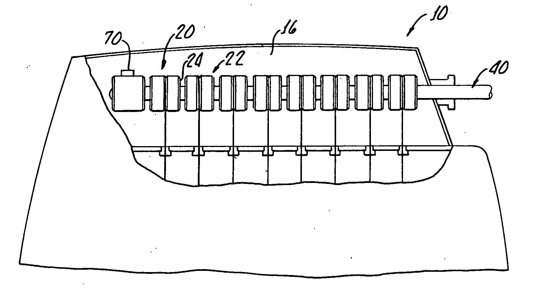
[0025] With reference to FIG. 1, there is shown spring contact apparatus 10 for an implantable medical device 12 which includes a header 16 along with a plurality of nonconductive housings 20, 22 each having a bores 24, 26 therethrough.

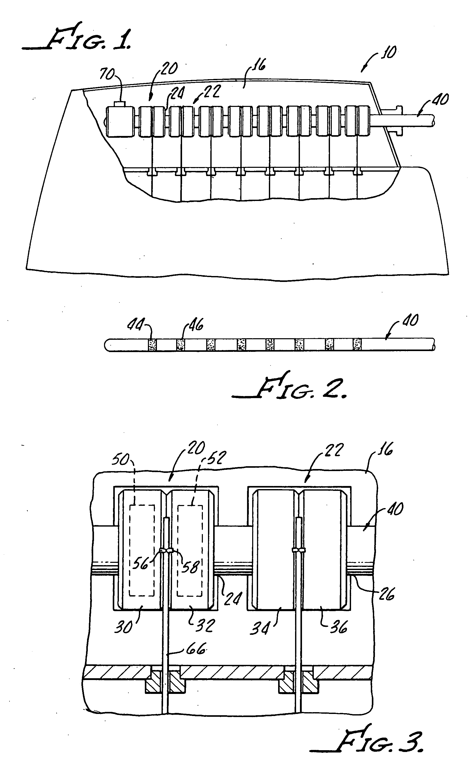
[0026] The housings 20, 22 are assembled in spaced apart pairs 30, 32 and 34, 36. A rod 40 is receivable by the housing bores 24, 26 and, as more clearly shown in FIG. 2, includes a plurality of spaced apart electrical terminals 44, 46 corresponding to the spaced apart housing pairs 20, 22.

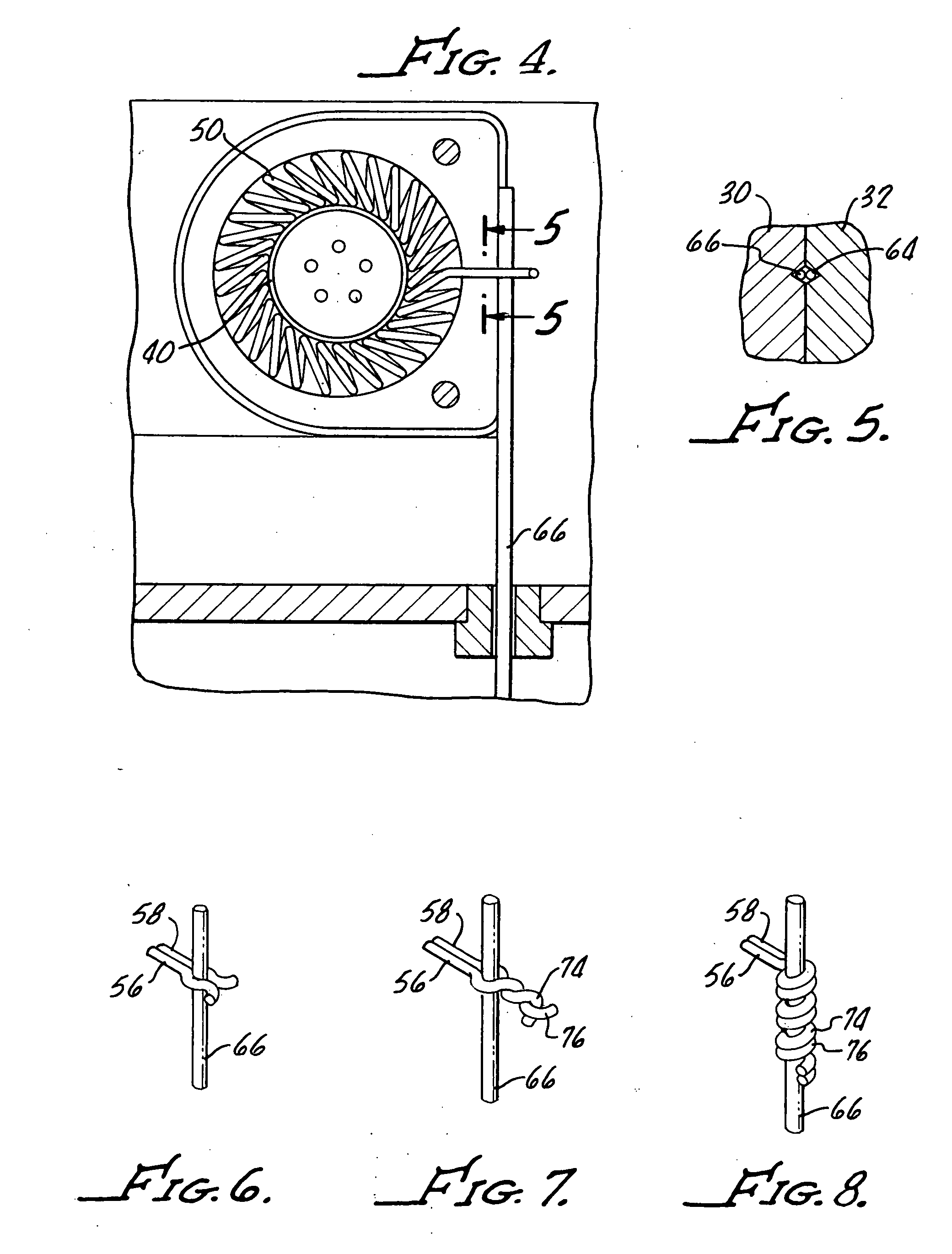
[0027] With reference to FIGS. 3-5, a plurality of electrically conductive garter springs 50 are disposed in corresponding adjacent housing chambers 30, 32, 34, 36 with each spring 50, 52 including adjacent pigtail leads 56, 58 extending from adjacent axes 62, 64 of the housings 30, 32 with sufficient length to enable combined attachment to a corresponding pulse generator lead 66.

[0028] Shown assembled in FIG. 1, with the rod 40 in position for maintaining electr...


PUM


Abstract

Spring contact apparatus for an implantable medical device includes a plurality of nonconductive housing with each housing having a bore therethrough alignable with adjacent housing bores and assembled in spaced apart pairs with adjacent radial accesses to adjacent housing chambers. A plurality of electrically conductive garter springs are provided with the pairs of garter springs being disposed in corresponding adjacent housing chambers and each spring having a pigtail lead extending through a corresponding axis. The pairs of adjacent pigtail leads extending from adjacent axes are of sufficient length for a combined attachment to a corresponding pulse generator lead.

Description

[0001] The present application claims priority from U.S. Ser. No. 60 / 619,862 which is incorporated herewith in its entirety by this subject reference thereto.[0002] This invention is generally directed to implantable medical devices and is more particularly directed to the electrical conductive path between a pulse generator and the implantable lead or leads. [0003] Implantable medical electronics devices consist of an implanted pulse generator that is used to provide electrical stimulation to certain tissues and an implantable lead or leads that are used to transmit the electrical impulse to the targeted tissues. The first ones were developed for cardiac pacemaking, and that area now has a number of applications for cardiac rhythm management, treatments for congestive heart failure, and implanted defibrillators. Other devices are used for neurostimulation with a wide range of uses such as pain control, nervous tremor mitigation, incontinent treatment, epilepsy seizure reduction, va...

Claims


Application Information

Patent Timeline
Patent Type & Authority Applications(United States)
IPC IPC(8): A61N1/375
CPCA61N1/3752
Inventor BALSELLS, PETER J.
Owner BAL SEAL ENG CO INC
Why Eureka
Try Eureka