Method of manufacturing a power module

a manufacturing method and power module technology, applied in the field of electronic packaging, can solve the problems of degrading the magnetic performance and efficiency of the magnetic devices, the overall efficiency of the power converter suffered well below an acceptable level, and the magnetic performance of the devices to degrad

Active Publication Date: 2006-05-11
INTEL CORP
View PDF38 Cites 50 Cited by
  • Summary
  • Abstract
  • Description
  • Claims
  • Application Information

AI Technical Summary

Benefits of technology

[0011] These and other problems are generally solved or circumvented, and technical advantages are generally achieved, by advantageous embodiments of the present invention which includes a method of manufacturing a power module on a substrate. In one embodiment, the method includes providing power conversion circuitry including providing a magnetic device having a magnetic core and at least one switch on the substrate. The method also includes placing a shielding structure over the magnetic core to create a chamber thereabout. The method also includes depositing an encapsulant about the power conversion circuitry. The shielding structure limits the encapsulant entering the chamber thereby allowing the encapsulant to surround a portion of the magnetic core within the chamber.

Problems solved by technology

However, in the pursuit of producing encapsulated, power converter packages (also referred to as “power modules”), it was discovered that the normally effective operation of encapsulating the power conversion circuitry with a conventional thermosetting epoxy molding compound through a conventional transfer molding process can degrade the magnetic performance and efficiency of the magnetic devices.
As a result, an overall efficiency of the power converter suffered well below an acceptable level.
More specifically, an underlying effect that occurs when magnetic devices are encapsulated (causing the magnetic performance of the devices to degrade) is magnetostriction.
Magnetostriction in the magnetic material causes degradation of magnetic properties when placed under tensile or compressive stress.
As a result, the electrical design of the power conversion circuitry suffers from both reduced inductance values and reduced quality factors (e.g., higher magnetic core losses).
First, most designs for power converters simply avoided the problem by remaining unencapsulated.
Unfortunately, the power converters were unable to take advantage of the physical protection and additional heat dissipating capacity that encapsulation provides.
The unencapsulated power converters were also difficult to mount on a circuit board due to a lack of suitable soldering processes and handling surfaces.
The power conversion circuitry of the unencapsulated power converters were also subject to detrimental exposure to washing processes during the manufacture thereof and to potentially damaging conditions in inhospitable environments.
While Lotfi provides a viable alternative to dealing with the stress upon a magnetic core from the encapsulant, it may be cumbersome to deposit the compliant material about the magnetic core in some applications.
While Manzione provides an alternative to direct excess molding compound away from the electronic device substrate, it may not viable to employ such a solution in some applications.

Method used


Image

  • Method of manufacturing a power module
  • Method of manufacturing a power module
  • Method of manufacturing a power module

Examples


Embodiment Construction

[0024] The making and using of the presently preferred embodiments are discussed in detail below. It should be appreciated, however, that the present invention provides many applicable inventive concepts that can be embodied in a wide variety of specific contexts. The specific embodiments discussed are merely illustrative of specific ways to make and use the invention, and do not limit the scope of the invention.

[0025] The present invention will be described with respect to preferred embodiments in a specific context, namely, an encapsulatable package for a magnetic device, a power module and a method of manufacture thereof. While the principles of the present invention will be described in the environment of a power converter, any application that may benefit from an encapsulatable package for a magnetic device is well within the broad scope of the present invention.

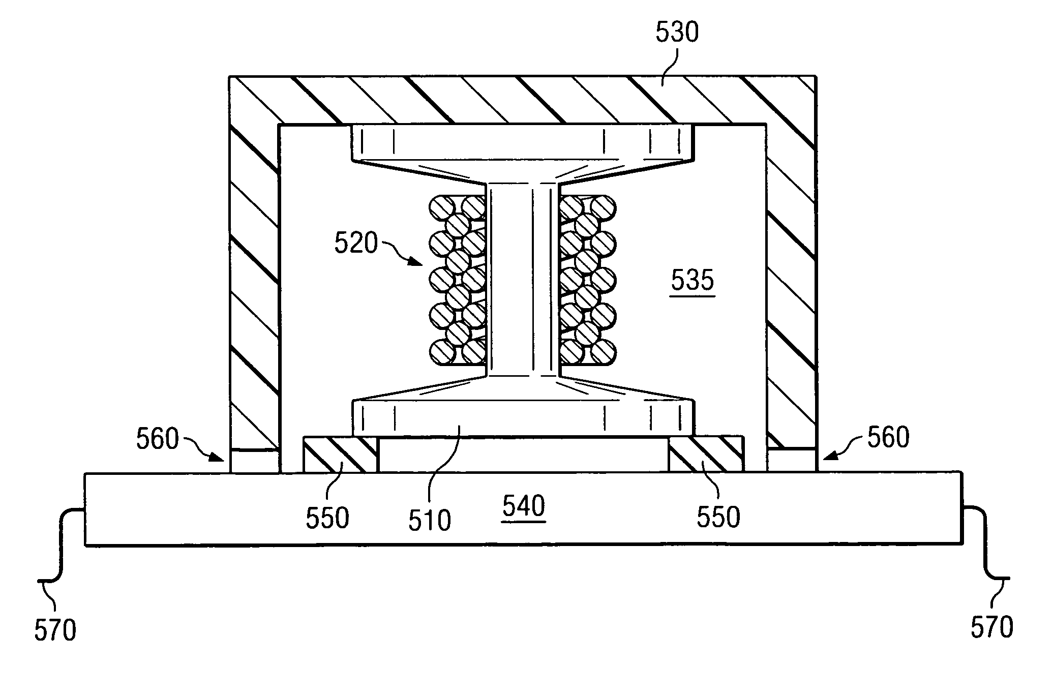
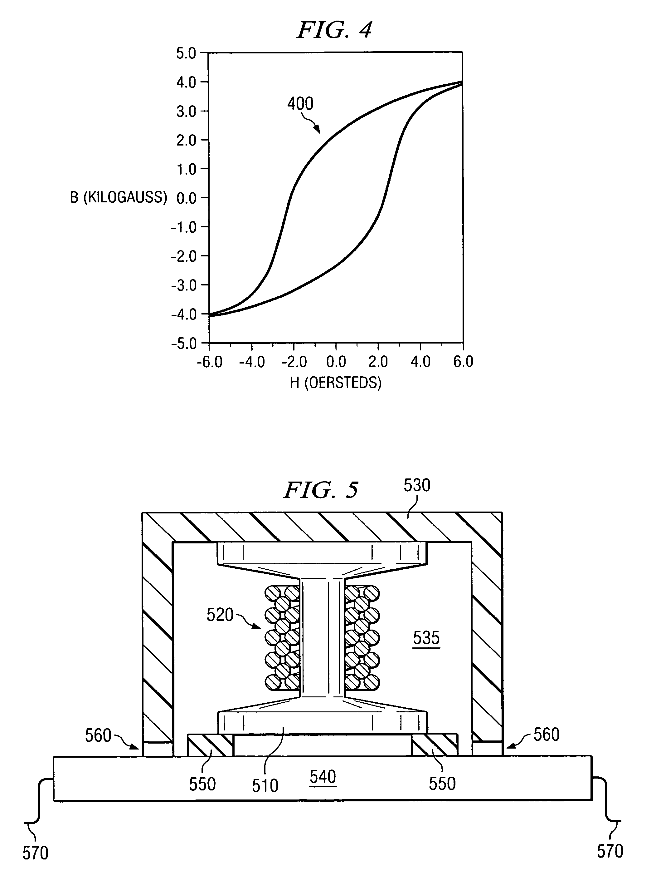
[0026] As will become more apparent, the encapsulatable package for the magnetic device includes a magnetic core an...


PUM

PropertyMeasurementUnit
coercivityaaaaaaaaaa
magnetic fieldaaaaaaaaaa
temperatureaaaaaaaaaa

Abstract

A method of manufacturing a power module on a substrate. In one embodiment, the method includes providing power conversion circuitry including providing a magnetic device having a magnetic core and at least one switch on the substrate. The method also includes placing a shielding structure over the magnetic core to create a chamber thereabout. The method also includes depositing an encapsulant about the power conversion circuitry. The shielding structure limits the encapsulant entering the chamber thereby allowing the encapsulant to surround a portion of the magnetic core within the chamber.

Description

TECHNICAL FIELD [0001] The present invention is directed, in general, to electronics packaging and, more specifically, to a method of manufacturing a power module. BACKGROUND [0002] A magnetic device uses magnetic material arranged to shape and direct magnetic flux in a predetermined manner to achieve a desired electrical performance. The magnetic flux provides a medium for storing, transferring or releasing electromagnetic energy. The magnetic devices typically include a core having a predetermined volume and composed of a magnetic material (e.g., ferrite) having a magnetic permeability greater than that of a surrounding medium (e.g., air). A conductive winding (or a plurality of conductive windings) of a desired number of turns and carrying an electrical current surround, excite and are excited by the magnetic core (or legs thereof). Inasmuch as the magnetic core usually has a relatively high permeability, magnetic flux produced by the conductive windings is generally confined alm...

Claims


Application Information

Patent Timeline
Patent Type & Authority Applications(United States)
IPC IPC(8): H05K3/30H05K3/10
CPCH01F17/043H01F27/027H01F27/255H01F27/365H01F41/005H05K3/284Y10T29/49069Y10T29/49002Y10T29/4913Y10T29/49073Y10T29/49171Y10T29/49155Y10T29/49146Y10T29/4902H01F27/36H01F27/363
Inventor LOTFI, ASHRAF W.WILKOWSKI, MATHEWWELD, JOHN D.
Owner INTEL CORP
Why Eureka
Try Eureka