
Eureka
For R&D, Eureka makes reading and utilizing patents & technical documents easy.
Eureka AIR
Designed for self-driven R&D workflows. Generate viable solutions, solve complex R&D challenges, empower your innovation with AI.

Eureka Materials
Designed for material experts only. Revolutionize your material R&D, from search, analyze, to developing new materials.

TechResearch
Generate reliable direction feasibility study reports for your R&D in just a few steps.

TechSeek
Discover and master advanced knowledge NOW. Basics, ideas, possibilities, all at once.

TechMind
As an expert in R&D Theories, TechMind can generates customized viable solutions instantly.

TechRisk
Analyze your overall solution with one click, know your potential R&D risks in advance.

TechMonitor
Get weekly tech updates, stay abreast of the latest tech innovations and key insights.
Motor driver
- Summary
- Abstract
- Description
- Claims
- Application Information
AI Technical Summary
Benefits of technology
Problems solved by technology
Method used
Image

Examples
first embodiment
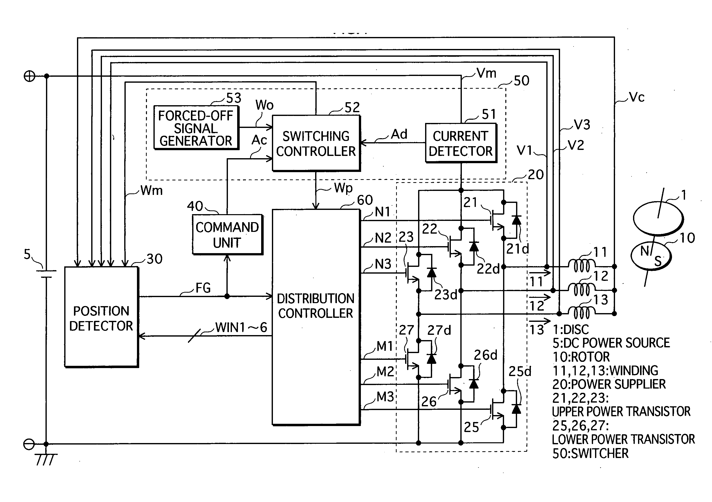
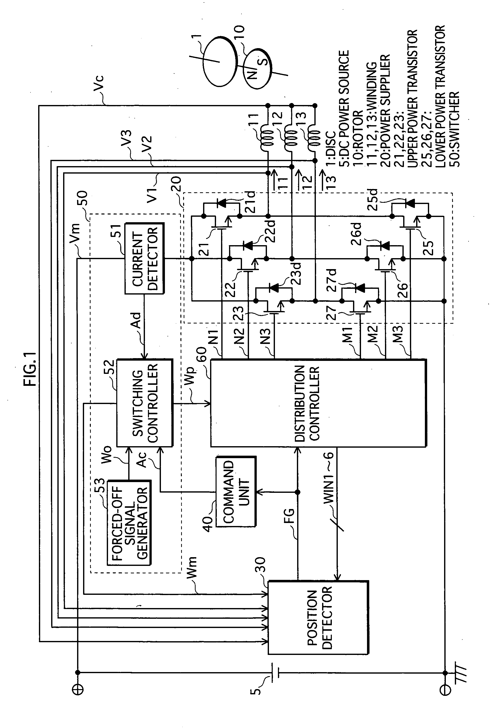
[0044]FIG. 1 shows the structure of a motor driver of the first embodiment.
[0045] In the figure, a rotor 10 has a magnetic field unit attached thereto which generates a plurality of magnetic field poles using permanent magnets. Three phase windings 11, 12, and 13 are mounted on stators, which are stationary parts, and are arranged so as to be electrically shifted by 120 degrees with respect to the rotor 10. One terminal of each winding is connected to a power supplier 20, and the other terminals are commonly connected. The three phase windings 11, 12, and 13 generate three phase magnetic flux according to three phase driving voltages I1, I2, and I3, and generate driving power according by mutual action with the rotor 10. This rotates the rotor 10 and a disc 1 mounted on the rotor 10.
[0046] A DC power source 5 is the source of power. The negative terminal of the DC power source 5 is connected to earth potential and the positive terminal of the DC power source 5 supplies required DC...
second embodiment
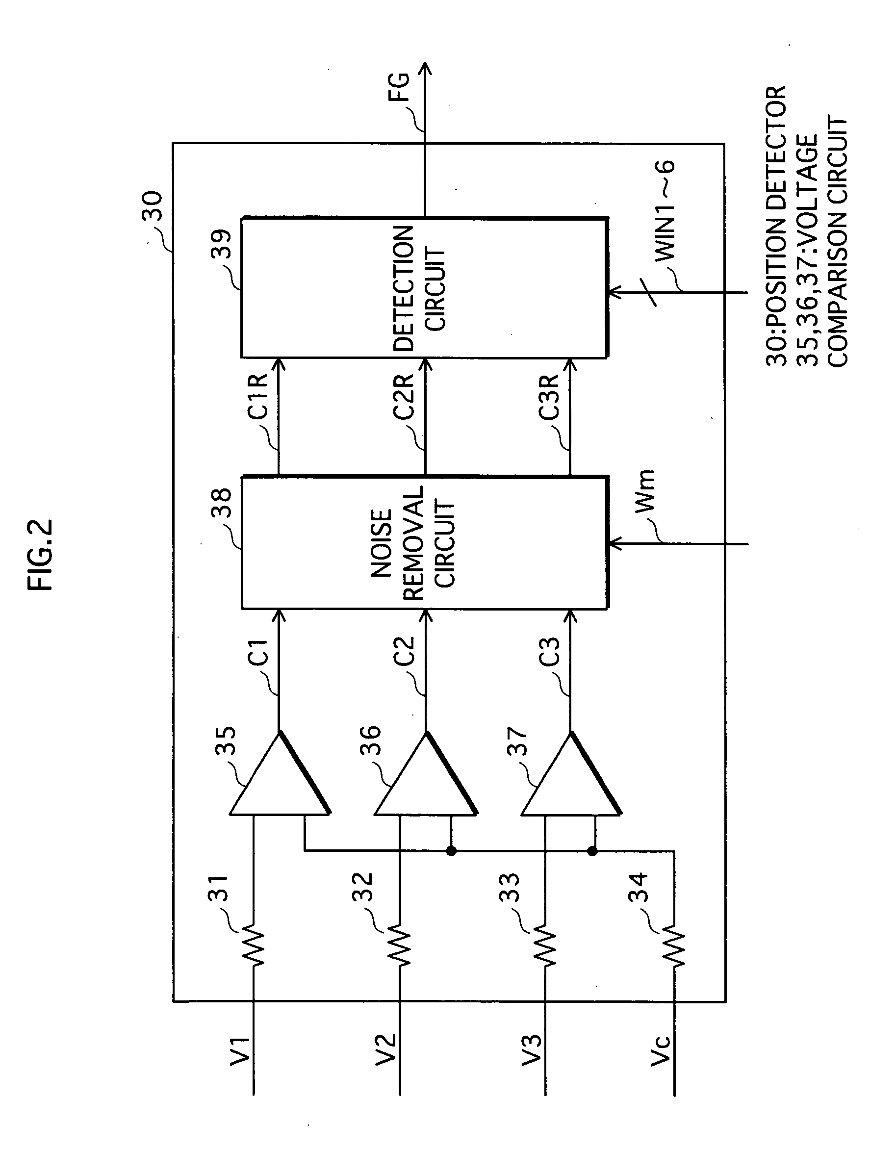
[0064]FIG. 5 shows the structure of a motor driver of the second embodiment. In the motor driver of FIG. 1, a center tap voltage Vc of a common connection point of the terminal voltages V1, V2, and V3 from one terminal of each of the three-phase windings 11, 12, and 13 is input into the position detector 30, and the position detector 30 detects the rotational position of the disc 1 and the rotor 10. In contrast, in the motor driver of the present second embodiment, only the terminal voltages V1, V2, and V3 of the three-phase windings 11, 12, and 13 are input into a position detector 30A, and the position detector 30A detects the rotational position without using the center tap voltage Vc.
[0065]FIG. 6 shows detailed structure of the position detector 30A. The terminal voltages V1, V2, and V3 that occur at one terminal of each of the three-phase windings 11, 12, and 13 are respectively input into the input terminals of the voltage comparison circuits 35, 36, and 37 via the input resi...
third embodiment
[0067]FIG. 7 shows the structure of the motor driver of the third embodiment.
[0068] The structure shown in FIG. 7 differs from that shown in FIG. 1 in that it additionally includes a rotation speed judgment unit 70.
[0069] The detection pulse signal FG from the position detector 30 is input into the rotation speed determination unit 70, and the rotation speed determination unit 70 determines the rotation speed of the disc 1 and the rotor 10 using the position detection pulse signal FG. When the rotation speed of the disc 1 and the rotor 10 is determined to be at least a predetermined speed, the rotation speed determination unit 70 outputs a high level rotation speed determination signal NS. Note that the structure for judging the rotation speed of the disc 1 and the rotor 10 is not limited to being a structure in which the position detection pulse signal FG is used in the judgment. Any other structure by which the rotation speed can be judged is possible.
[0070]FIG. 8 shows detaile...
PUM
 Abstract
Description
Claims
Application Information
 - R&D Engineer
- R&D Manager
- IP Professional
- Industry Leading Data Capabilities
- Powerful AI technology
- Patent DNA Extraction
Browse by: Latest US Patents, China's latest patents, Technical Efficacy Thesaurus, Application Domain, Technology Topic, Popular Technical Reports.
© 2024 PatSnap. All rights reserved.Legal|Privacy policy|Modern Slavery Act Transparency Statement|Sitemap|About US| Contact US: help@patsnap.com