Screen, image projection system having the screen, and method of manufacturing the screen

a technology of image projection system and screen, which is applied in the field of screen, image projection system having the screen, and the method of manufacturing the screen, can solve the problems of affecting the naturalness of the projected image, difficult to join the multiple regions together to produce the large screen, and inability to perform high-quality image projection. achieve the effect of wide viewing angle characteristics, high image brightness and high accuracy

Inactive Publication Date: 2006-05-11
YAMAUCHI NAOFUMI
View PDF2 Cites 14 Cited by
  • Summary
  • Abstract
  • Description
  • Claims
  • Application Information

AI Technical Summary

Benefits of technology

[0007] It is therefore an object of the present invention to provide a screen for a projector with which even when an image area is increased by dividing a screen configuration element into multiple regions, it becomes possible to project a natural image, in which seams are inconspicuous, while maintaining directionality, wide viewing angle characteristics, and high image brightness. It is also an object of the present invention to provide a manufacturing method with which it becomes possible to manufacture the projector screen at low cost with high accuracy.
[0008] The screen according to the present invention is constructed by joining a surface diffusion sheet, which approximately isotropically diffuses incoming light at its surface, and a directional diffusion sheet, which has a large scattering effect with respect to light incident at a predetermined angle and has a small scattering effect with respect to light incident from other directions, together in this order from an observer's view point side. The surface diffusion sheet has a not-divided and single-sheet configuration and the directional diffusion sheet has a structure in which it is divided into multiple regions. With the structure, even when a large screen is formed using a directional scattering sheet divided into multiple regions, boundaries between the divided regions become difficult to visually recognize due to a diffusion action of the surface diffusion sheet, and more natural image projection becomes possible. In addition, it becomes easy to arrange a directional diffusion sheet adjusted in diffusion characteristics and divided into multiple regions on a screen as appropriate, and it becomes possible to improve the viewing angle characteristics and brightness distribution of a projected image.

Problems solved by technology

The large screen realized by joining multiple regions together, however, has a problem that seams between the regions are conspicuous and therefore the naturalness of a projected image is impaired, and it is impossible to perform high-quality image projection.
Also, it is difficult to join the multiple regions together to produce the large screen.

Method used


Image

  • Screen, image projection system having the screen, and method of manufacturing the screen
  • Screen, image projection system having the screen, and method of manufacturing the screen
  • Screen, image projection system having the screen, and method of manufacturing the screen

Examples


embodiment

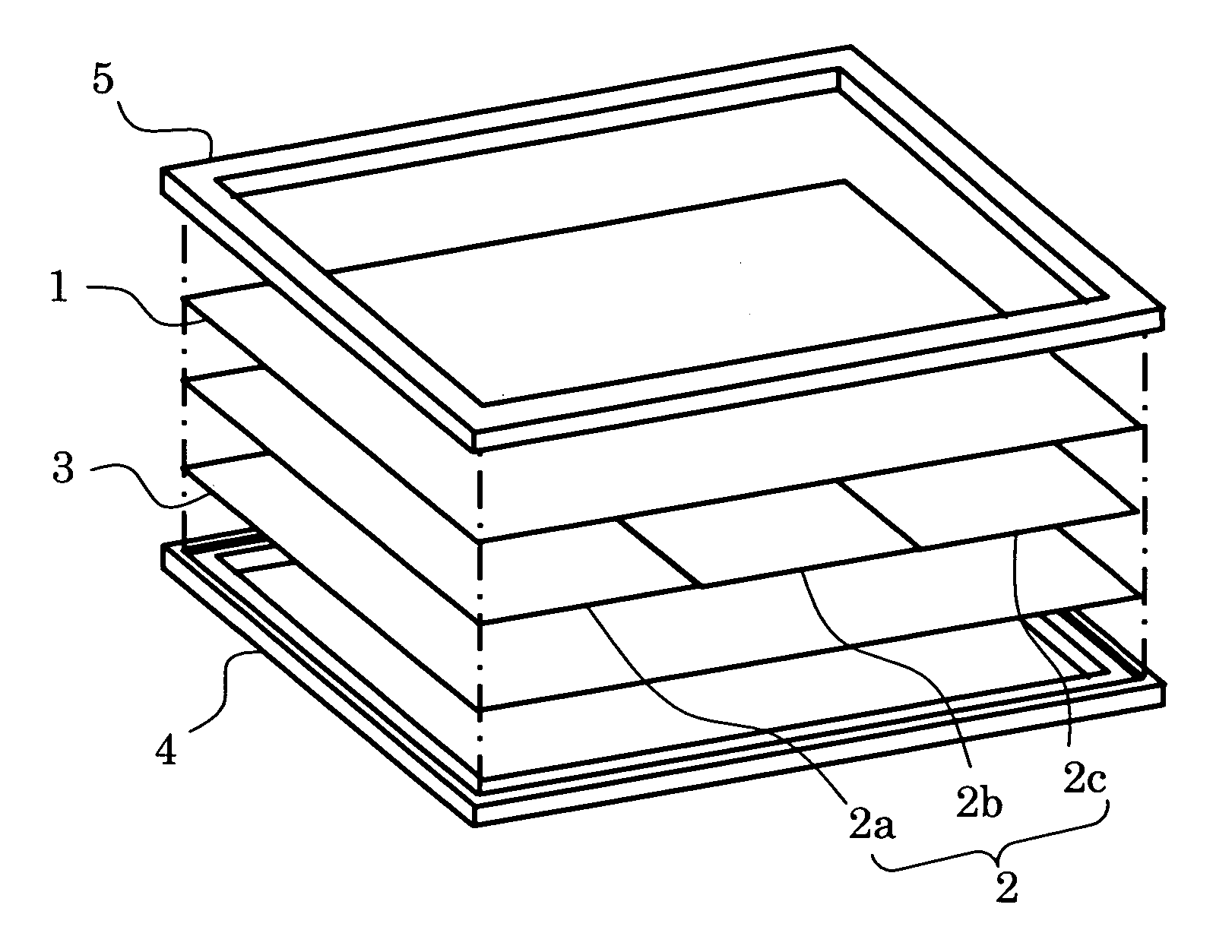
[0028] Hereinafter, a screen in this embodiment will be described with reference to the accompanying drawings. FIG. 1 is a schematic perspective arrangement view of the screen in this embodiment. Referring to FIG. 1, in an image projection portion of the screen, a surface diffusion sheet 1, a directional diffusion sheet 2, and a light reflecting sheet 3 are laminated and joined together in order. In this embodiment, the directional diffusion sheet 2 includes three divided regions 2a, 2b, and 2c. The number of the divided regions is determined by the size of the screen and the characteristics of the directional diffusion sheet to be described later, and therefore it is not necessarily required to include three regions.

[0029] Also, the screen has a configuration in which the surface diffusion sheet 1, the directional diffusion sheet 2, and the light reflecting sheet 3 are arranged in this order from an observer's view point side. A projector that is applicable to the screen is not li...

concrete example

[0085] A screen shown in FIG. 1 having the surface diffusion sheet, the directional diffusion sheet, and the light reflecting sheet was formed. As the directional diffusion sheet, a sheet having a columnar structure with a sheet thickness of 70 μm and a diameter of 50 μm was used. The orientation angle of the columnar structure was set at zero degrees. Also, as the light reflecting sheet, a sheet obtained by vacuum-depositing Ag onto a surface of a polyethylene sheet to have a thickness of around 200 nm was used.

[0086] The directional diffusion sheet was divided into two regions and a joining gap between the regions was changed. That is, two directional diffusion sheets were bonded onto the light reflecting sheet, a joining gap between the two directional diffusion sheets was measured with a scale of a microscope, and then the surface diffusion sheet was bonded to a surface of the directional diffusion sheet. In this example, samples respectively using surface diffusion sheets with...


PUM


Abstract

A large-area projector screen, whose joining gaps are inconspicuous, and a method of producing the screen are provided. The screen according to the present invention is produced by arranging and bonding a surface diffusion sheet having a predetermined haze value and approximately isotropically diffuses incoming light and multiple directional diffusion sheets together. Here, the directional diffusion sheets have a large scattering effect with respect to light incident at a predetermined angle and have a small scattering effect with respect to light incident from other directions. As a result, even when a large screen is formed using a directional scattering sheet divided into multiple regions, boundaries between the divided regions become difficult to visually recognize due to a diffusion action of the surface diffusion sheet and more natural image projection becomes possible.

Description

BACKGROUND OF THE INVENTION [0001] 1. Field of the Invention [0002] The present invention relates to a screen onto which an optical image from a high brightness CRT, a liquid crystal projector, or the like is projected, an image projection system having the screen, and a method of manufacturing the screen. [0003] 2. Description of the Related Art [0004] Image projection systems, such as projector devices, which display images by projecting optical images using high brightness CRTs, liquid crystal projectors, or the like can simply and easily display high definition images on large screens, and therefore are being used as information communication tools among multiple users in various ways. As disclosed in JP 11-52107 A, for instance, the light utilization efficiency of a conventional screen used in such an image projection system is improved using a structure, in which a white color material or a reflective film is coated onto a surface of the screen, and the visibility of the scree...

Claims


Application Information

Patent Timeline
Patent Type & Authority Applications(United States)
IPC IPC(8): G03B21/60
CPCG03B21/60G03B21/56
Inventor YAMAUCHI, NAOFUMI
Owner YAMAUCHI NAOFUMI
Why Eureka
Try Eureka