Polarization beam splitter and liquid crystal projector apparatus

a polarization beam and splitter technology, applied in the direction of polarizing elements, picture reproducers using projection devices, instruments, etc., can solve the problem of difficult implementation of expected polarization splitting performance, and achieve the effect of enhancing the polarization splitting function and high performan

Inactive Publication Date: 2006-05-11
SONY CORP
View PDF8 Cites 17 Cited by
  • Summary
  • Abstract
  • Description
  • Claims
  • Application Information

AI Technical Summary

Benefits of technology

[0032] From the foregoing, the polarization beam splitter can be implemented with a higher performance.
[0033] Further, assurance of a space which makes the air layer on the metal grid side can be implemented readily by a structure that the first and second glass prisms are fixed at upper and bottom faces of the pole-like members thereof to fixing plates or by another structure that end portions of the opposing...

Problems solved by technology

However, the polarization beam splitter disclosed in Patent Document 1 has such problems as ...

Method used


Image

  • Polarization beam splitter and liquid crystal projector apparatus
  • Polarization beam splitter and liquid crystal projector apparatus
  • Polarization beam splitter and liquid crystal projector apparatus

Examples


Embodiment Construction

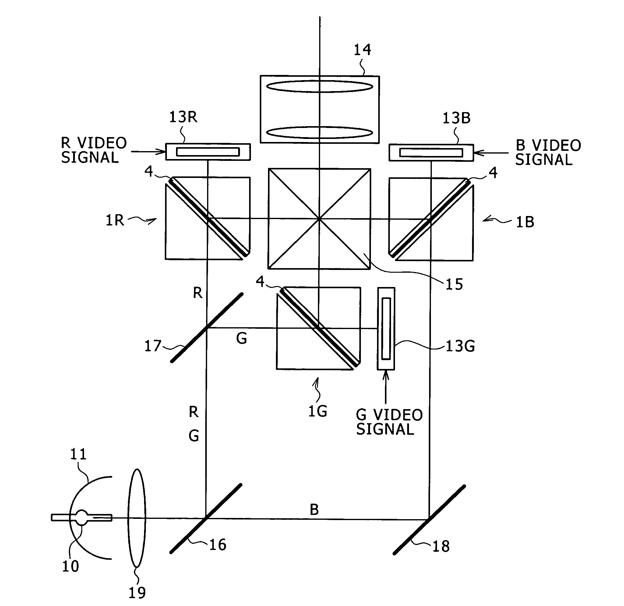
[0051] In the following, several polarization beam splitters to which the present invention is applied and several liquid crystal projector apparatus in which the polarization beam splitters are used are described.

[0052] First, a basic configuration of a polarization beam splitter to which the present invention is applied is described with reference to FIGS. 1A to 2B.

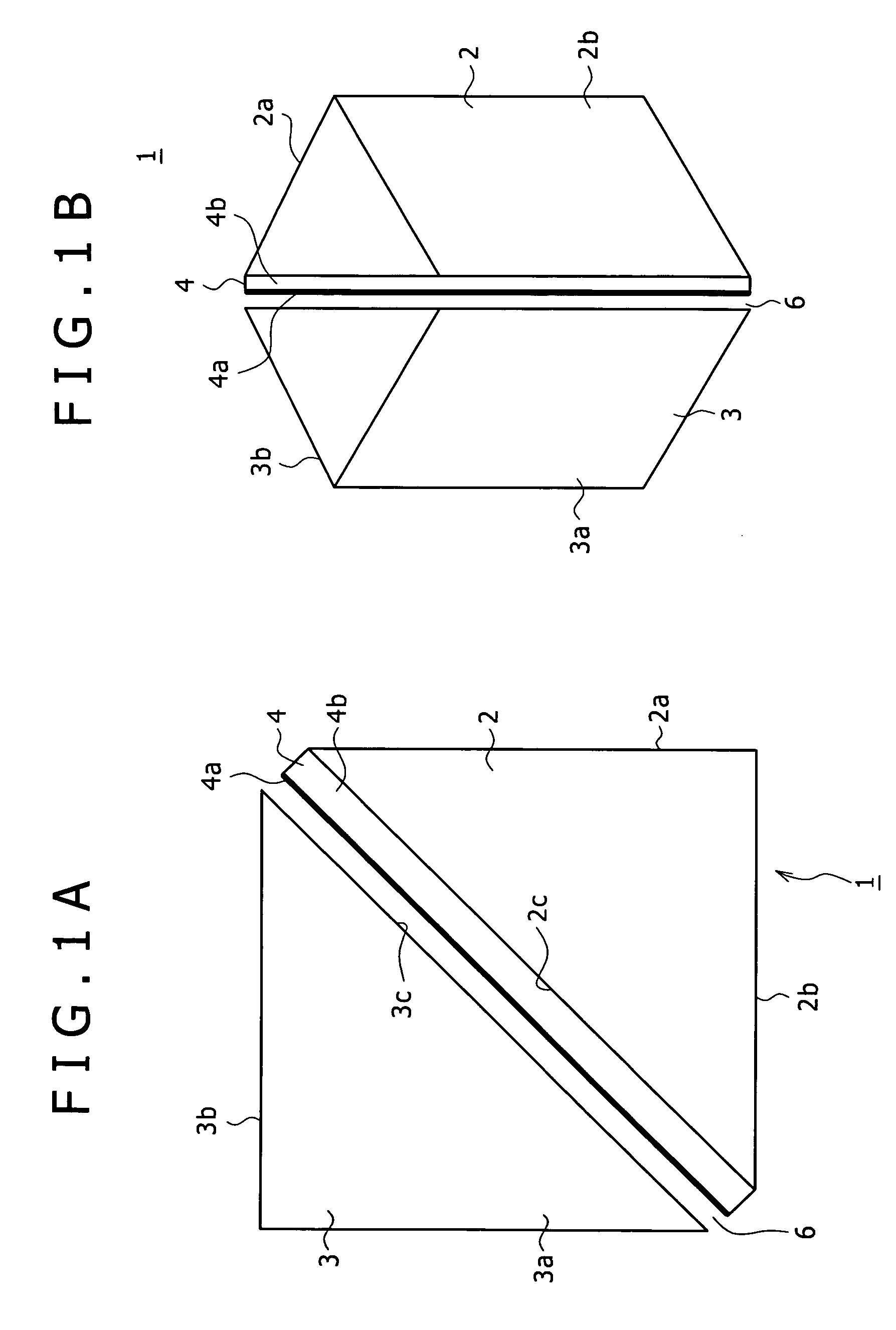
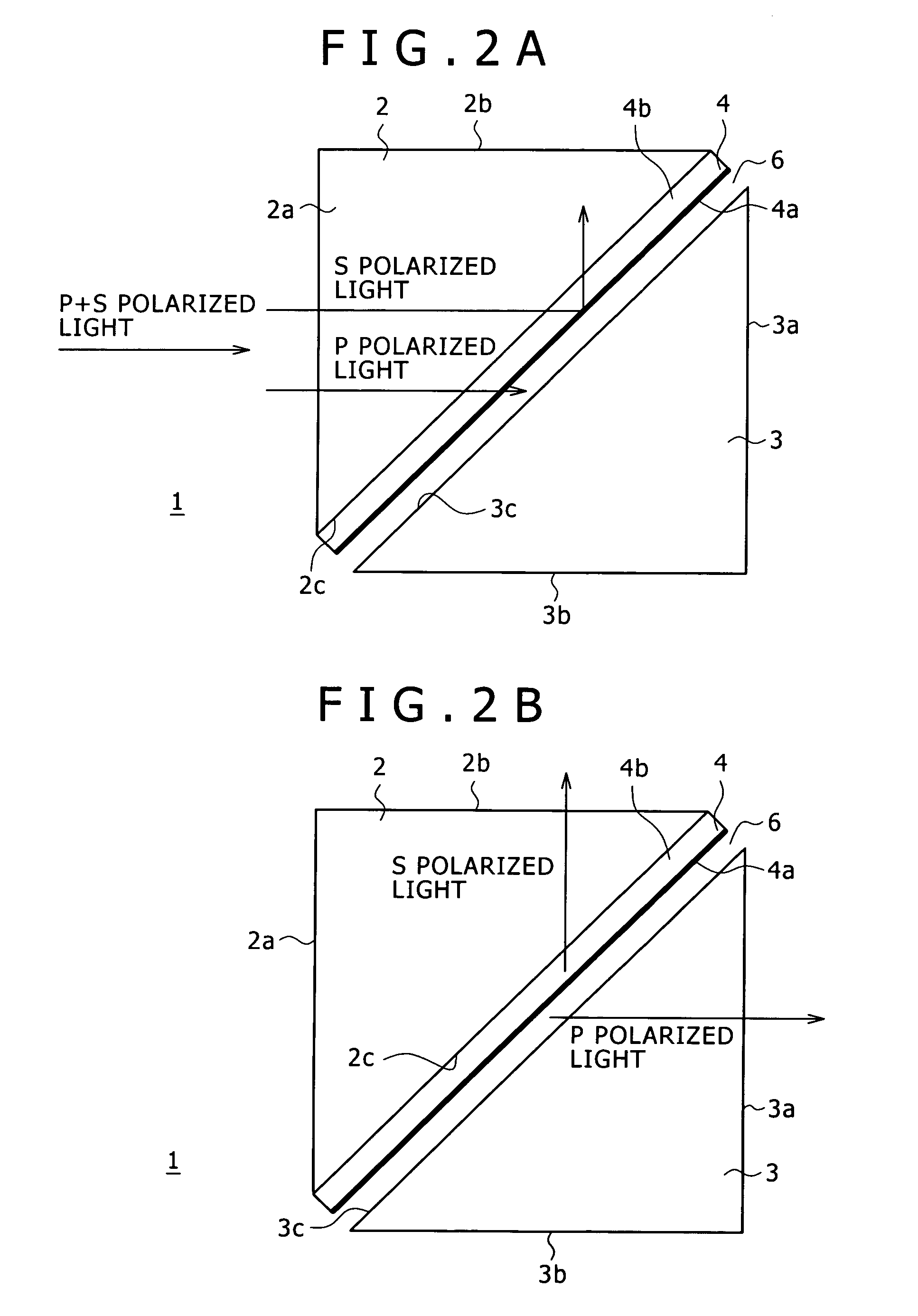
[0053] The polarization beam splitter 1 of the present embodiment shown includes a pair of glass prisms 2 and 3 each formed from a pole-like member and a wire grid polarization splitting device 4. Particularly, the glass prisms 2 and 3 are formed as right isosceles triangular prisms.

[0054] The glass prism 2 has three side faces 2a, 2b and 2c which correspond to the three sides of a right isosceles triangular shape. Each of the side faces2a and 2b functions as an incoming face or an outgoing face when the polarization beam splitter 1 is disposed on a light path. The side face 2c functions as an opposing face opposed t...


PUM


Abstract

A polarization beam splitter having an enhanced polarization splitting characteristic is disclosed. The polarization beam splitter includes a first glass prism formed from a pole-like member having side faces which include first and second end faces each of which functions as an incoming face or an outgoing face of light and an opposing face; a second glass prism formed from a pole-like member having side faces which include first and second end faces each of which functions as an incoming face or an outgoing face of light and an opposing face; and a wire grid polarization splitting device formed from a glass substrate and a metal grid formed on a face of the glass substrate; the wire grid polarization splitting device being fixed, at a face of the glass substrate thereof on which the metal grid is not formed, to the opposing face of the first glass prism; the second glass prism being disposed so as to oppose, at the opposing face thereof, to the opposing face of the first glass prism to which the wire grid polarization splitting device is fixed in such a manner that an air layer is formed between the opposing faces.

Description

BACKGROUND OF THE INVENTION [0001] This invention relates to a polarization beam splitter which splits an incoming light flux into two orthogonally and linearly polarized light fluxes and transmits and emits one of the linearly polarized lights but reflects the other linearly polarized light to perform polarization splitting. The invention further relates to a liquid crystal projector apparatus in which the polarization beam splitter is used. [0002] A liquid crystal projector apparatus of the type described is disclosed, for example, in Japanese Patent Laid-Open No. 2003-131212 (hereinafter referred to as Patent Document 1). [0003] In a reflection type liquid crystal projector apparatus in which a reflection type liquid crystal panel is used, an incoming portion and an outgoing portion of light to and from the liquid crystal panel are same as each other. Therefore, it is necessary to perform polarization splitting using a polarization beam splitter or a like device. [0004]FIG. 12A s...

Claims


Application Information

Patent Timeline
IPC IPC(8): G02B5/30G02B27/28G03B21/20H04N9/31
CPCG02B5/3058G02B27/283H04N9/3105H04N9/315H04N9/3197G03B21/2073G02B5/04G02F1/1335
Inventor SATO, YOSHIHISA
Owner SONY CORP
Why Eureka
Try Eureka