Illumination assembly using circuitized strips

a technology of illumination assembly and circuitized strips, which is applied in the direction of semiconductor devices for light sources, lighting and heating apparatus, lighting support devices, etc., can solve the problems of difficult manufacturing or assembly, difficult to produce printed circuit boards, and difficult to meet the size and shape requirements of some display devices

Active Publication Date: 2006-05-11
3M INNOVATIVE PROPERTIES CO
View PDF6 Cites 96 Cited by
  • Summary
  • Abstract
  • Description
  • Claims
  • Application Information

AI Technical Summary

Problems solved by technology

However, when LEDs are required to be distributed over a large area (as when backlighting a large high performance display device, for example), the use of a printed circuit board becomes problematic for several reasons.
For example, printed circuit boards may be difficult to produce and / or handle in the sizes and shapes required for some display devices (e.g., very long and narrow strips).
The rigidity of the printed circuit board material may make manufacturing or assembly difficult, especially where the printed circuit board must conform to a non-planar shape.
Additionally, the heat dissipation requirements of the LEDs may not be met by conventional printed circuit board constructions.

Method used


Image

  • Illumination assembly using circuitized strips
  • Illumination assembly using circuitized strips
  • Illumination assembly using circuitized strips

Examples


Embodiment Construction

[0017] In the following description, reference is made to the accompanying drawings. The reader will understand that other embodiments can be utilized and structural or logical changes may be made. The following detailed description, therefore, is not to be taken in a limiting sense, and the scope of the present invention is defined by the appended claims.

[0018] As used herein, the terms “LED” and “light emitting diode” are used to refer generally to light emitting semiconductor elements with contact areas for providing power to the diode. Different forms of inorganic semiconductor light emitting diodes may be formed, for example, from a combination of one or more Group III elements and of one or more Group V elements (III-V semiconductor). Examples of III-V semiconductor materials that can be used in an LED include nitrides, such as gallium nitride or indium gallium nitride, and phosphides, such as indium gallium phosphide. Other types of III-V materials can also be used, as can i...


PUM


Abstract

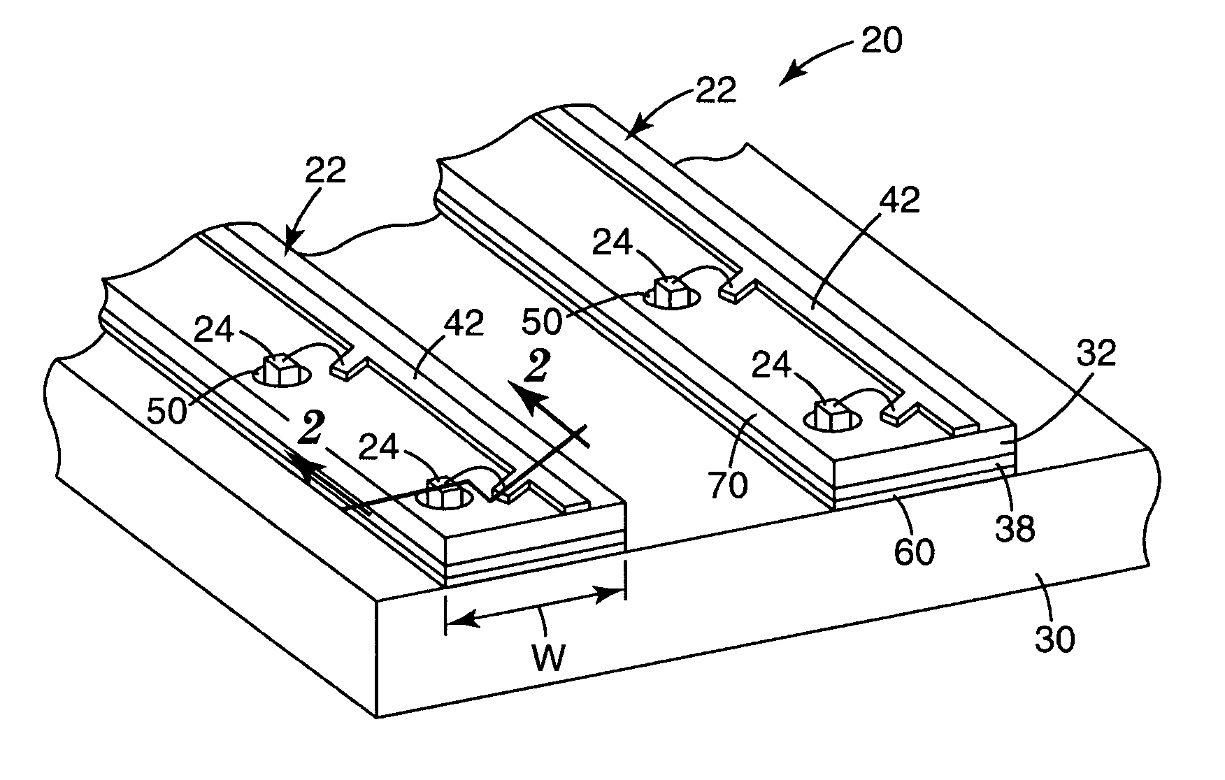
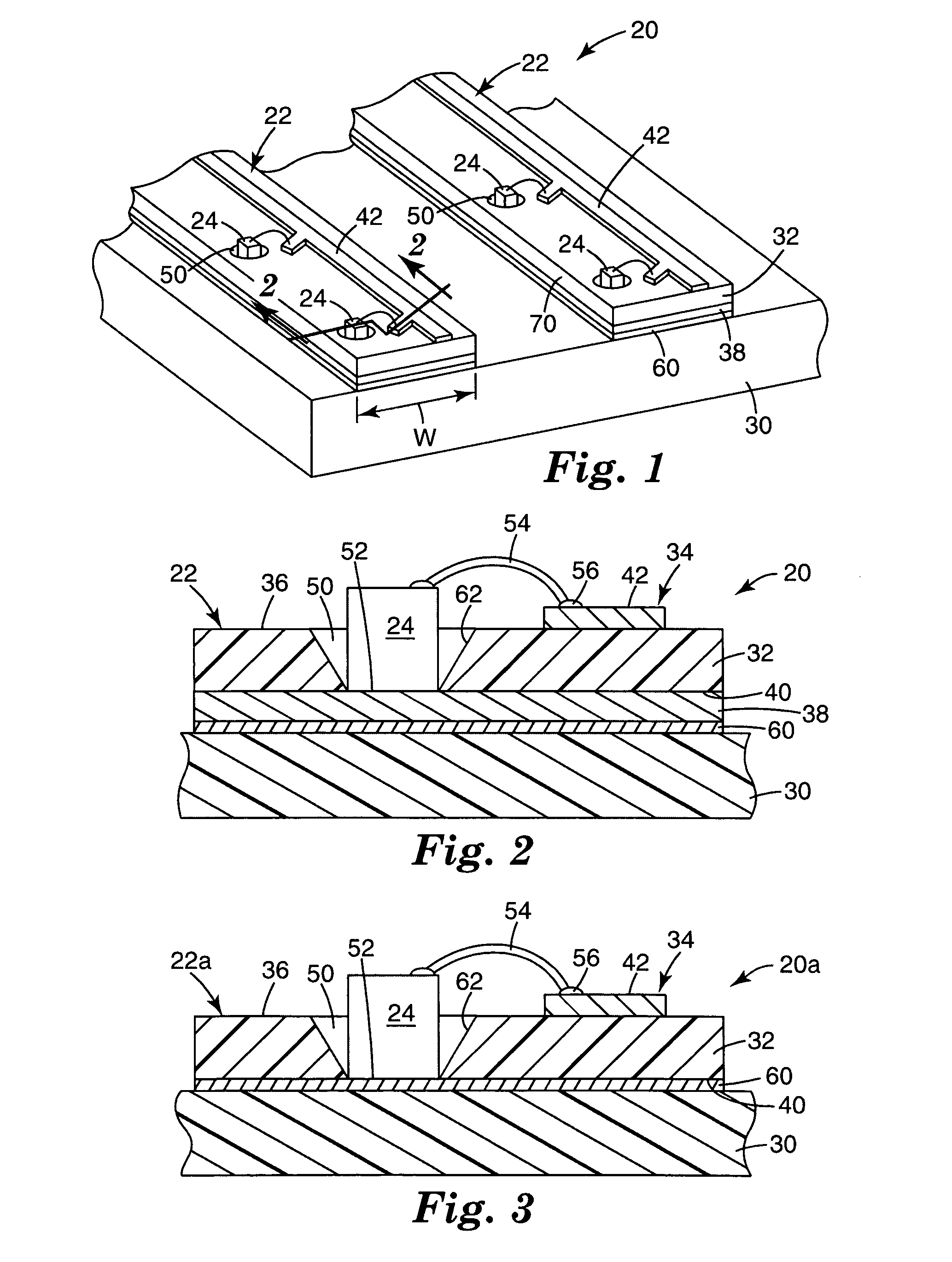
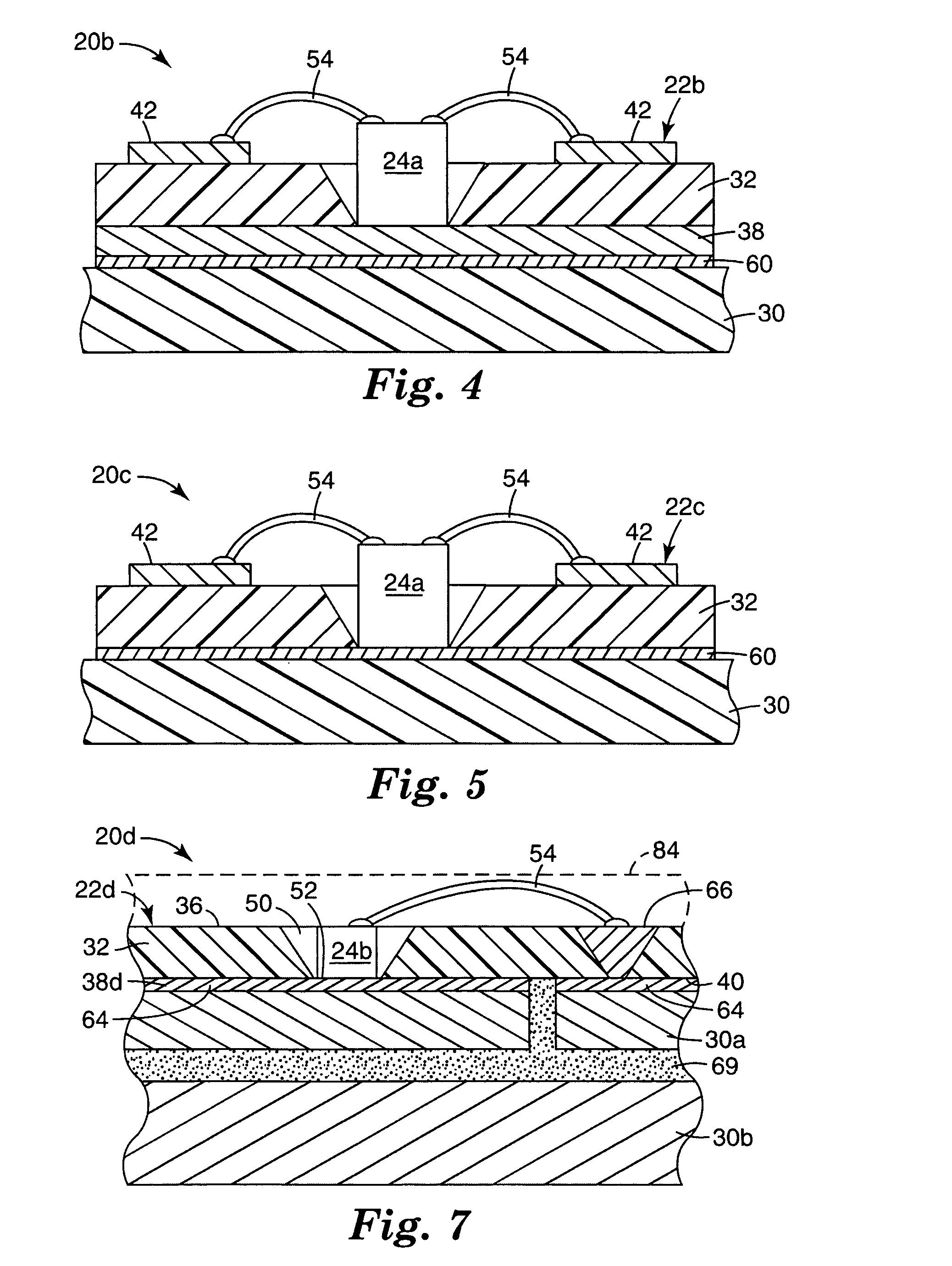
An illumination assembly includes a heat dissipating member having a plurality of circuitized strips disposed thereon a spaced relationship. Each circuitized strip includes an electrically insulative substrate having at least one circuit trace on a first side of the substrate and an electrically and thermally conductive layer on a second side of the substrate, such that the at least one circuit trace is electrically insulated from the second side of the substrate. The circuitized strips have a plurality of vias extending from the first side to the second side of the substrate. A plurality of LEDs are disposed in the plurality of vias, such that each LEDs is disposed on the electrically and thermally conductive layer on the second side of the substrate and electrically connected to the at least one circuit trace on the first side of the substrate.

Description

BACKGROUND [0001] The present invention generally relates to a lighting or illumination assembly. More particularly, the present invention relates to a lighting or illumination assembly that uses an array of light emitting diodes (LEDs). [0002] Illumination systems are used in a variety of diverse applications. Traditional illumination systems have used lighting sources such as incandescent or fluorescent lights, for example. More recently, other types of light emitting elements, and light emitting diodes (LEDs) in particular, have been used in illumination systems. LEDs have the advantages of small size, long life and low power consumption. These advantages of LEDs make them useful in many diverse applications, and LEDs are frequently replacing other lighting sources. [0003] For many lighting applications, it is necessary or desirable to have a plurality of LEDs supply the required light intensity and / or distribution. For example, a plurality of LEDs can be assembled in an array ha...

Claims


Application Information

Patent Timeline
Patent Type & Authority Applications(United States)
IPC IPC(8): F21V29/00F21K99/00H01L33/62
CPCH01L2924/3025H05K1/0203H05K1/182H01L2224/48091H01L2924/00014F21K9/00H01L33/62H01L2224/48227H01L2924/01079H01L2924/15153H01L2924/1517H01L2924/01322H01L2924/12041Y10S362/80H05K3/0097H05K2201/066H05K2201/10106
Inventor OUDERKIRK, ANDREW J.AESCHLIMAN, DENNY G.TRAN, HUNG T.EPSTEIN, KENNETH A.MEIS, MICHAEL A.SCHULTZ, JOHN C.
Owner 3M INNOVATIVE PROPERTIES CO
Why Eureka
Try Eureka