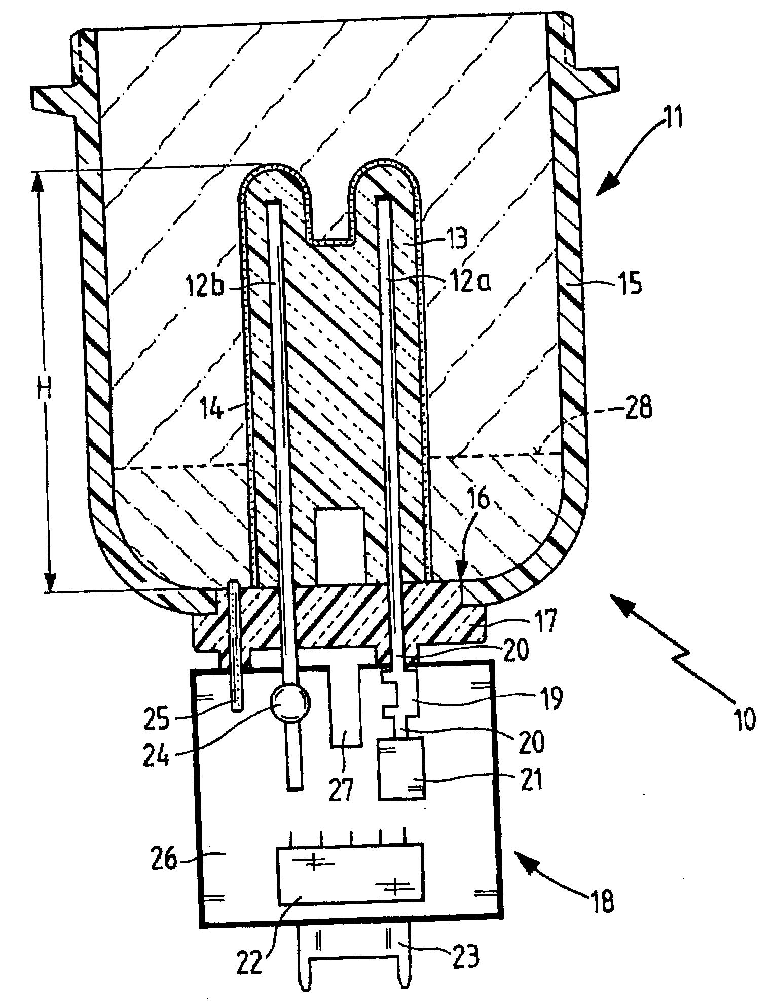
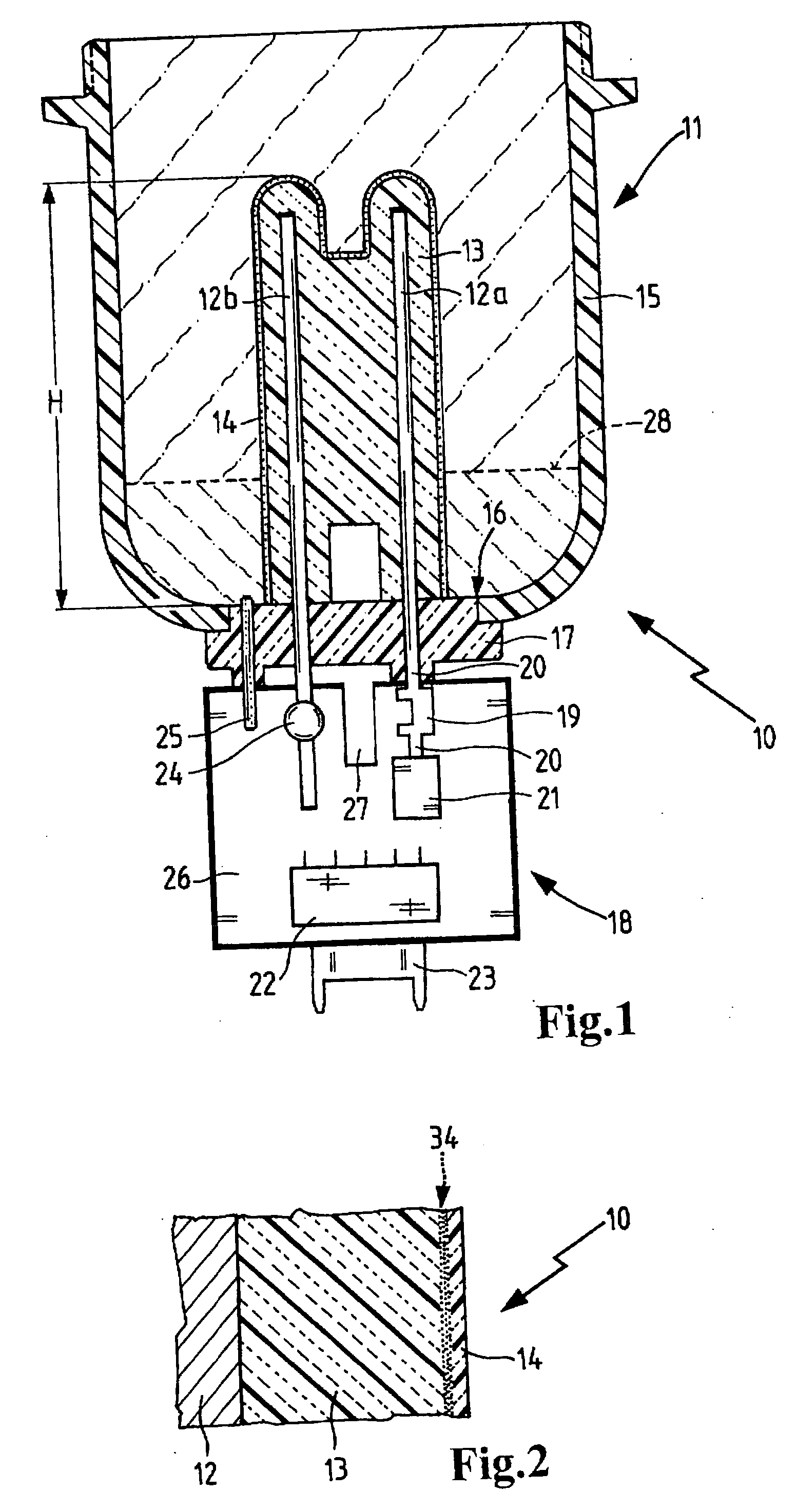
[0041]FIG. 1 shows a resistance heater 10 which is arranged on a housing 11. The housing 11 can be integrated into a fuel system via a flange (not shown). Resistance heater 10 has contact rods 12a and 12b, which are sheathed directly on their surfaces by a heating element 13. Contact rods 12a and 12b are made of a material which is a very good conductor of heat and electricity, in particular a metal such as copper.
[0042] The heating element 13 is arranged so it stands upright inside the housing 11 and extends over a height range H. The heating element 13 is formed by a material that conducts heat and electricity well, preferably a conductive synthetic resin (i.e. plastics) material. A plastic resistor material is especially suitable due to its properties. The plastic resistor material is made of a synthetic resin such as polyamide, polyphenylenesulfide or polypropylene using electrically conducting particles such as metals, carbon fibers, carbon black, graphite or a combination of these materials as fillers. The type and amount of filler may be selected according to the electric resistance desired. The plastic essentially retains its specific gravity and strength and can be processed by methods conventionally used for plastics, such as injection molding. The surface of the heating element 13 is surrounded by a thin wall of electrically insulating layer 14.
[0043] The housing 11 has a housing wall 15 on which a housing opening 16 is provided in a deep area. The contact rods 12a and 12b pass through an adaptor 17 which is inserted into the housing opening 16 and closes the opening in a tightly sealed manner. The adaptor 17 is preferably made of a polymer which has thermal and electric insulation properties. To ensure the imperviousness of the housing opening 16, a resilient seal (not shown) may be arranged between the adaptor 17 and the housing wall 15. The seal may be attached axially and/or in the direction of assembly or also around the periphery, on the adaptor 17 and/or on the housing 11. An analyzer unit 18 is arranged beneath the adaptor 17. The contact rods 12a, 12b extend beneath the adaptor 17 into the analyzer unit 18 and are attached to it, for example, by soldered connections, by screw connections, or by plug-in connections.
[0044] A melting fuse 19 which serves as overheating protection is provided on the analyzer unit 18. The melting fuse 19 is connected to the contact rod 12a and a switching transistor 21 via connecting elements 20, thereby coupling it thermally to the resistance heater. The connecting elements 20 may be plug-in connections, solder joints or screw connections. The melting fuse 19 is made of an alloy with a low melting point. Depending on the current flow, overheating of the resistance heater is prevented by the melting fuse 19 by interrupting the current flow.
[0045] The switching transistor 21 which is also arranged on the analyzer unit 18 switches the heating element 13 on and off, controlled by a control pulse; this is known as pulse-width modulation (PWM). The switching transistor 21 is connected to the contact rod 12a. Due to this connection, heat generated in the switching transistor 21 can be dissipated into the heating element 13 via the contact rod 12a.
[0046] Another electronic component 22, which may be a microprocessor, for example, is provided on the analyzer unit 18 for detecting and processing all the values detected. An electric plug connector 23 forms a corresponding plug-in connection to an electronic unit, for example, and a power supply (not shown). A temperature sensor 24 is attached directly to the contact rod 12b with the largest possible surface contact, thereby ensuring a good heat transfer to the temperature sensor 24. The contact rod 12b is thermally connected to the temperature sensor 24, preferably by soldering. In other embodiments, the attachment may be undetachable, e.g., by adhesive bonding or riveting or detachable, e.g., by a plug-in connection or screw connection.
[0047] A contact plate 25 forms the electric contact surface with the liquid in the housing 11. Contact plate 25 is also connected to the analyzer unit 18. This makes it possible for an electric voltage pulse to be delivered by the analyzer unit 18 to the liquid and for the current and voltage characteristics to also be detected via the contact plate 25. The contact plate 25 may be attached in several positions and may be designed, e.g., in the form of a rod, a sheet metal strip or a cable. In the illustrative embodiment shown here, the contact plate 25 is located at the low point in the housing 11 and extends through the adaptor 17. However, the contact plate 25 may equally well be situated at a higher point and positioned separately in the housing 11.
[0048] The functional elements of the analyzer unit 18 described above are arranged directly or indirectly on a carrier body 26. For example a traditional plastic circuit board is a suitable carrier body 26 for the analyzer unit 18. The carrier body 26 has a recess or notch 27 which serves to provide thermal isolation and minimizes the transfer of heat emitted by the switching transistor 21 to the temperature sensor 24.
[0049] Inside the housing 11, there are two liquid media, each having a different density. The medium having the higher density is deposited in the lower area of the housing 11, and a phase boundary 28 is formed between the two media. In the case of a water separator for separating water from diesel fuel, the phase boundary 28 is detected by the analyzer unit 18. If the phase boundary 28 exceeds a defined limit value, then the accumulated water can be discharged from the housing 11 through a drain valve (not shown). The drain valve may also be situated in adaptor 17, for example, and triggered by the analyzer unit 18.
[0050]FIG. 2 shows as a detail an edge area of the resistance heater 10. This edge area is situated inside the housing 11 shown in FIG. 1. The heated element 13 is connected to the contact rod 12 on one side and is coated with the insulating layer 14 on the other side. Between the insulating layer 14 and the heating element 13, a surface seal 34 made of a hardened inorganic nonmetallic coating solution, in particular based on silicate, is provided. This surface seal 34 seals the polymer surface and thus prevents liquids from penetrating through it.
[0051]FIG. 3 shows the voltage characteristics of the filling level measurement at various liquid levels. The voltage characteristics are plotted on the voltage axis U as a function of the time axis t. The three curves 29, 30, 31 show the respective voltage characteristics for three different water levels of the liquid to be measured. In the voltage characteristics, the measurement is performed after the point in time 33. The values A, B and C detected at points in time 33 allow a conclusion as to the level of the liquid in the housing 11. If the amount of water in the housing 11 is high, the voltage characteristic curve 31 is shallow until the point in time 33 and yields the value C at the point in time 33. If there is no water in the housing 11, the voltage characteristic curve 30 climbs steeply until the point in time 33 yielding the value A. At a moderate water level, the voltage characteristic curve 29 is obtained with the value B.
[0052]FIG. 4 shows a temperature difference Δ between liquid temperature F inside the housing 11 (according to FIG. 1) and a sensor temperature S. This temperature difference Δ occurs at a constant velocity of flow and constant heating power. The temperature is shown as a function of the time t. At an activation point in time t0, the sensor temperature S is equal to the liquid temperature F. Between the activation time of the heating element at the point in time t0 and a delay time t1, the liquid temperature F rises to the sensor temperature S with a time lag. After the point in time t1, a constant temperature difference Δ is established between the sensor S and the liquid F. The sensor may also be situated outside the housing 11, which is also shown in FIG. 1, like the temperature sensor 24 shown in FIG. 1. The liquid temperature F can thus be calculated from the temperature value S detected at the sensor by subtracting the temperature difference Δ from the sensor temperature S.
[0053] The foregoing description and examples have been set forth merely to illustrate the invention and are not intended to be limiting. Since modifications of the described embodiments incorporating the spirit and substance of the invention may occur to persons skilled in the art, the invention should be construed broadly to include all variations within the scope of the appended claims and equivalents thereof.