Medical needle and medical device

a technology of medical devices and needles, applied in the field of medical needles, can solve the problems of unfavorable patient treatment, unfavorable patient treatment, and unfavorable patient treatment, and achieve the effect of minimizing damage to the pierced portion of the patient and reducing pain for the patien

Active Publication Date: 2006-05-11
LIGHTNIX
View PDF20 Cites 126 Cited by
  • Summary
  • Abstract
  • Description
  • Claims
  • Application Information

AI Technical Summary

Benefits of technology

[0039] A medical needle according to one of the aspects of the present invention reduces pain to the patient and minimizes damage to the pierced portion of the patient.

Problems solved by technology

The patient having such an injection needle or lancet pierced into the body, especially children, sometimes suffers unendurable pain or uncomfortableness.
Also, a substantial area of cells around the tingled portion may often be damaged, requiring some time to be healed.
To this end, the peripheral cells are extremely deformed by the physical stress due to the frictional force, and may often be burst away (collapsed) so that a pain-producing chemical mediator such as histamine and bradykinin is released within the tissue, thereby hurting the patient.
As described above, the conventional injection needle is highly invasive to pierce the tissue of the patient.

Method used


Image

  • Medical needle and medical device
  • Medical needle and medical device
  • Medical needle and medical device

Examples


embodiment 1

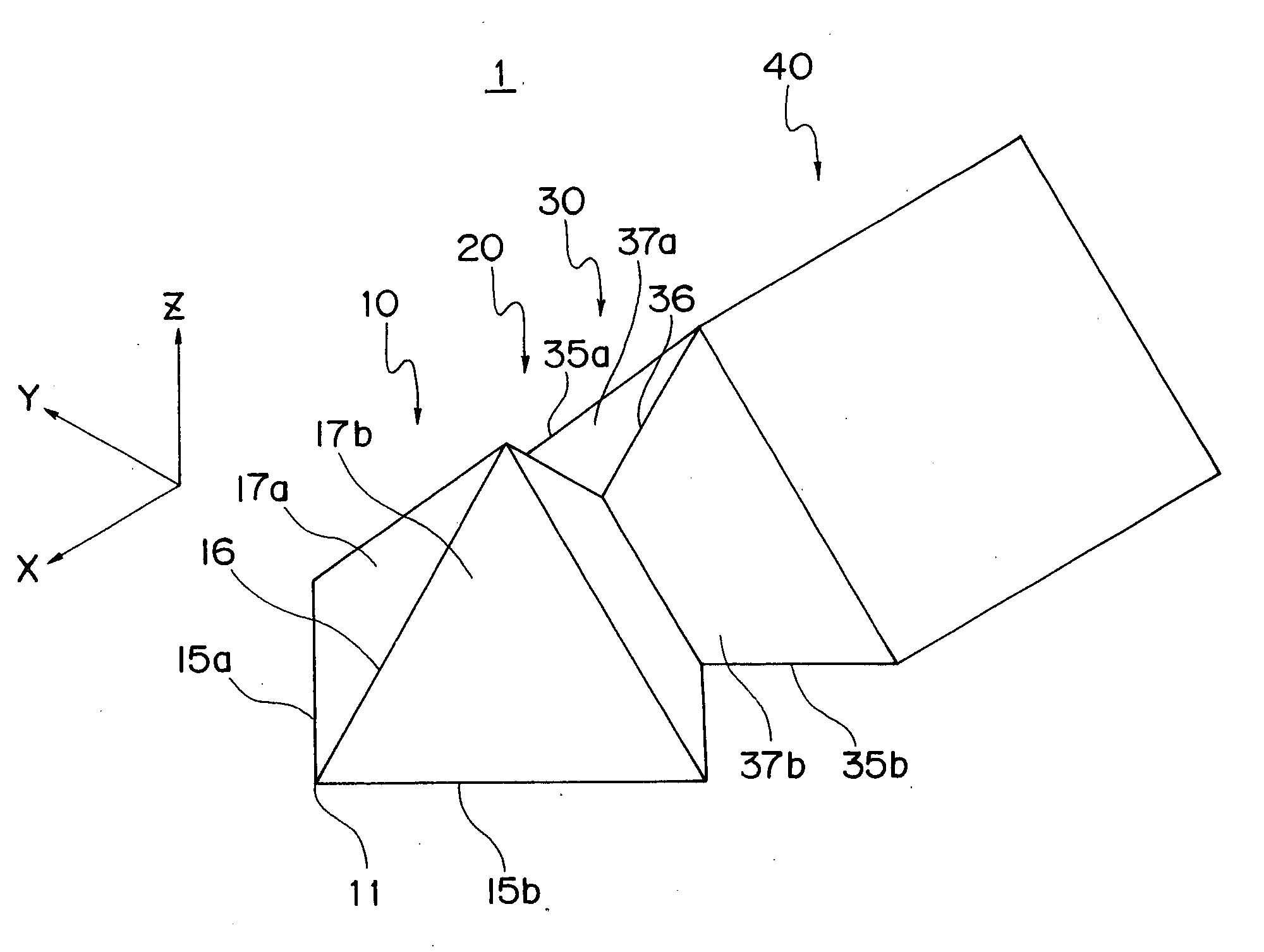
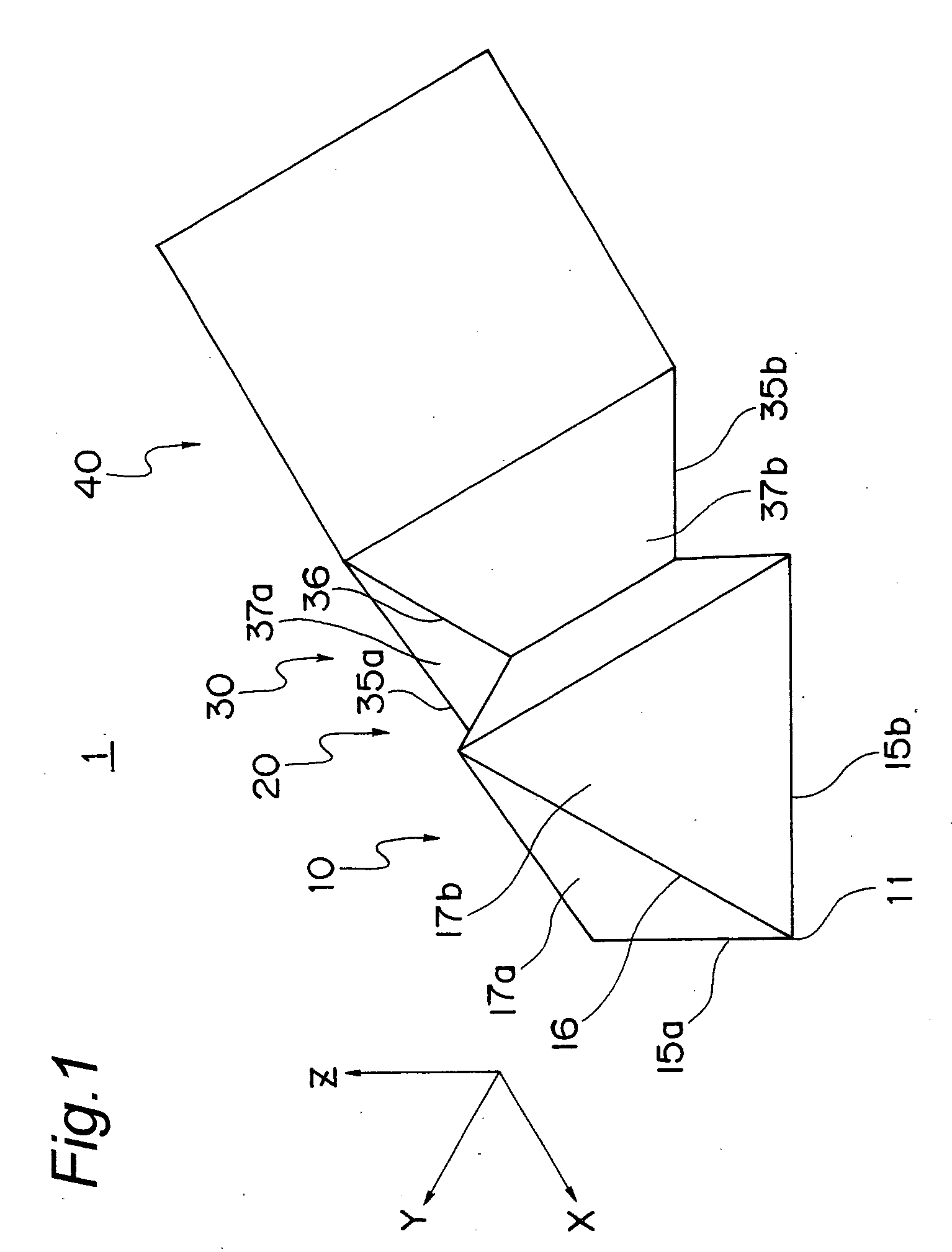
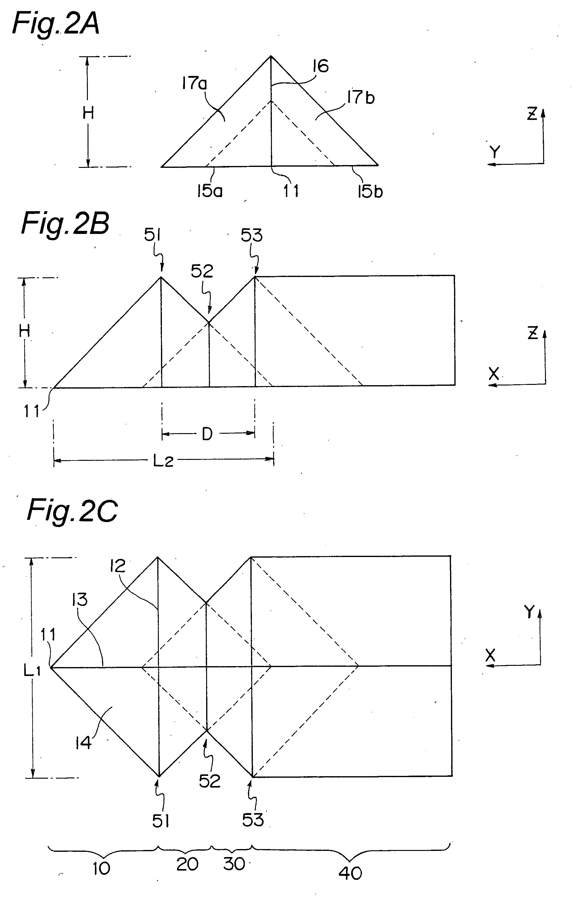
[0074] With reference to FIGS. 1 to 4, the first embodiment of the lancet according to the present invention will be described herein. The lancet 1 is used to sample a drop of blood of a patient such as a diabetic for measurement of blood sugar by stinging it onto the appropriate portion (e.g., fingertip) of the patient's body. As illustrated in FIGS. 1 and 2, the lancet 1 extends along the X-direction and has a triangle cross-section as taken along any Y-Z planes. The triangle cross-section includes a base, height, and area varying in accordance with the distance from a lancet tip 11 or the position of the X-axis. Thus, the lancet 1 includes a first ascending region (first tissue incising region) 10 of which area is monotonically increased as being away from the tip 11, a first descending region (first friction releasing region) 20 of which area is monotonically decreased as being away from the tip 11, and a second ascending region (second tissue incising region)30. A holding regio...

embodiment 2

[0097] With reference to FIGS. 6 to 9, the second embodiment of the lancet according to the present invention will be described herein. The lancet 2 of the second embodiment is similar to the lancet 1 of the first embodiment except that it additionally includes a constant region (reinforcing region). Therefore, the duplicated description in detail for the common features will be eliminated.

[0098] As above, the lancet 2 of the second embodiment has a constant region (reinforcing region) 60 for reinforcing the strength of the lancet 2 between the first descending region 20 and the second ascending region 30 as shown in FIGS. 6 and 7. The constant region 60 has an outer configuration of a triangular prism having a size of X-, Y-, and Z-directions (lx, ly, lz) with a triangular base 61 that is substantially the same shape and size as the smallest cross-section in the descending region 20. Thus, the constant region 60 has a triangle cross-section having a base (ly) and a height (lz) as ...

embodiment 3

[0101] With reference to FIG. 10, the third embodiment of the lancet according to the present invention will be described herein. The lancet 3 of the third embodiment is similar to the lancet 1 of the first embodiment except that the lancet tip is formed sharper than that of the first embodiment. Therefore, the duplicated description in detail for the common features will be eliminated.

[0102] In FIGS. 10B and 10C, the first and second ascending region 10, 30 are designed so as to have the triangular cross-section taken along any Y-Z planes, of which height and base are increased linearly as being away from the tip 11 with gradients (increasing rates) indicated by a solid line 55 and a one-dotted line 54, respectively. Also, the increasing rate (k) of the height and base of the first ascending region 10 indicated by the solid line 55 varies from an increasing rate (k1) indicated by one imaginary line 56 to another increasing rate (k2) indicated by another imaginary line 57, i.e.,

k2...


PUM


Abstract

One of aspects of the present invention is to provide a medical needle extending along a predetermined direction and having a vertical cross-section taken along a plane perpendicular to the predetermined direction of which cross-sectional area varies based upon a distance from a needle tip. The medical needle includes a plurality of maximal points where the cross-sectional area of the vertical cross-section is locally maximal, and a plurality of minimal points where the cross-sectional area of the vertical cross-section is locally minimal. The vertical cross-section at the maximal point closest to the needle tip has the cross-sectional area not less than those at any other maximal points.

Description

TECHNICAL FIELD [0001] The present invention relates to a medical needle such as a lancet and an injection needle and to a medical device using thereof, and in particular, relates to the medical needle made of biocompatible material and to the medical device using thereof. BACKGROUND ART [0002] In general, when a patient has a hypodermic injection, an injection needle is shot at an appropriate portion of the body such as skin and muscle to inject medicine inside the patient. Also, a diabetic uses a lancet to sample a small amount of his or her blood by stinging it on any suitable portions, e.g., at fingertip, for routine measurement of blood sugar. The patient having such an injection needle or lancet pierced into the body, especially children, sometimes suffers unendurable pain or uncomfortableness. Also, a substantial area of cells around the tingled portion may often be damaged, requiring some time to be healed. Therefore, there has been long-felt desire to develop a less invasiv...

Claims


Application Information

Patent Timeline
Patent Type & Authority Applications(United States)
IPC IPC(8): A61B17/14A61B5/15A61B17/32A61M5/32A61M5/42
CPCA61B5/1411A61M5/3286A61M5/422A61B5/150022A61B5/150099A61B5/150106A61B5/150229A61B5/150396A61B5/150404A61B5/150419A61B5/150427A61B5/150458A61B5/150503A61B5/150282A61B5/150412A61B5/150511A61M5/158
Inventor FUKUDA, MITSUOAOYAGI, SEIJI
Owner LIGHTNIX
Why Eureka
Try Eureka