Method and system for simulating and modeling a batch manufacturing facility

Inactive Publication Date: 2006-05-11
APPLIED PROCESS TECH
View PDF13 Cites 8 Cited by
  • Summary
  • Abstract
  • Description
  • Claims
  • Application Information

AI Technical Summary

Benefits of technology

[0030]FIGS. 10-11 illustrate a high-level proce

Problems solved by technology

The process for producing biopharmaceuticals is complex.
The production of biopharmaceuticals is complex because of the number, complexity and combinations of synthesis methods and processing steps possible.
Consequently, the design of a biopharmaceutical plant is expensive.
Tens of millions of dollars can be misspent during the design and construction phases of biopharmaceutical plants due to inadequacies in the design process.
Errors and inefficiencies are introduced in the initial design of the biopharmaceutical production process because no effective tools for modeling and simulating a biopharmaceutical production process exists.
Errors in the basic production process design propagate through all of the design and construction phases, resulting in increased cost due to change orders late in the facility development project.
For example, detailed piping and instrumentation diagrams (P&IDs) normally cost thousands of dollars per diagram.
Problems in the biopharmaceutical production process design frequently necessitate the re-working of these detailed P&IDs.
This adds substantially to the overall cost of design and construction of a biopharmaceutical plant.
Often the production process design is repeated for each phase, resulting in increased costs to each phase of plant development.
The unit operation level production process is typically designed by hand and is prone to errors and inefficiencies.
Often, in the conceptual design phase, the specifications for the final production process are not complete.
These factors

Method used


Image

  • Method and system for simulating and modeling a batch manufacturing facility
  • Method and system for simulating and modeling a batch manufacturing facility
  • Method and system for simulating and modeling a batch manufacturing facility

Examples


Embodiment Construction

[0056] A description of preferred embodiments of the invention follows.

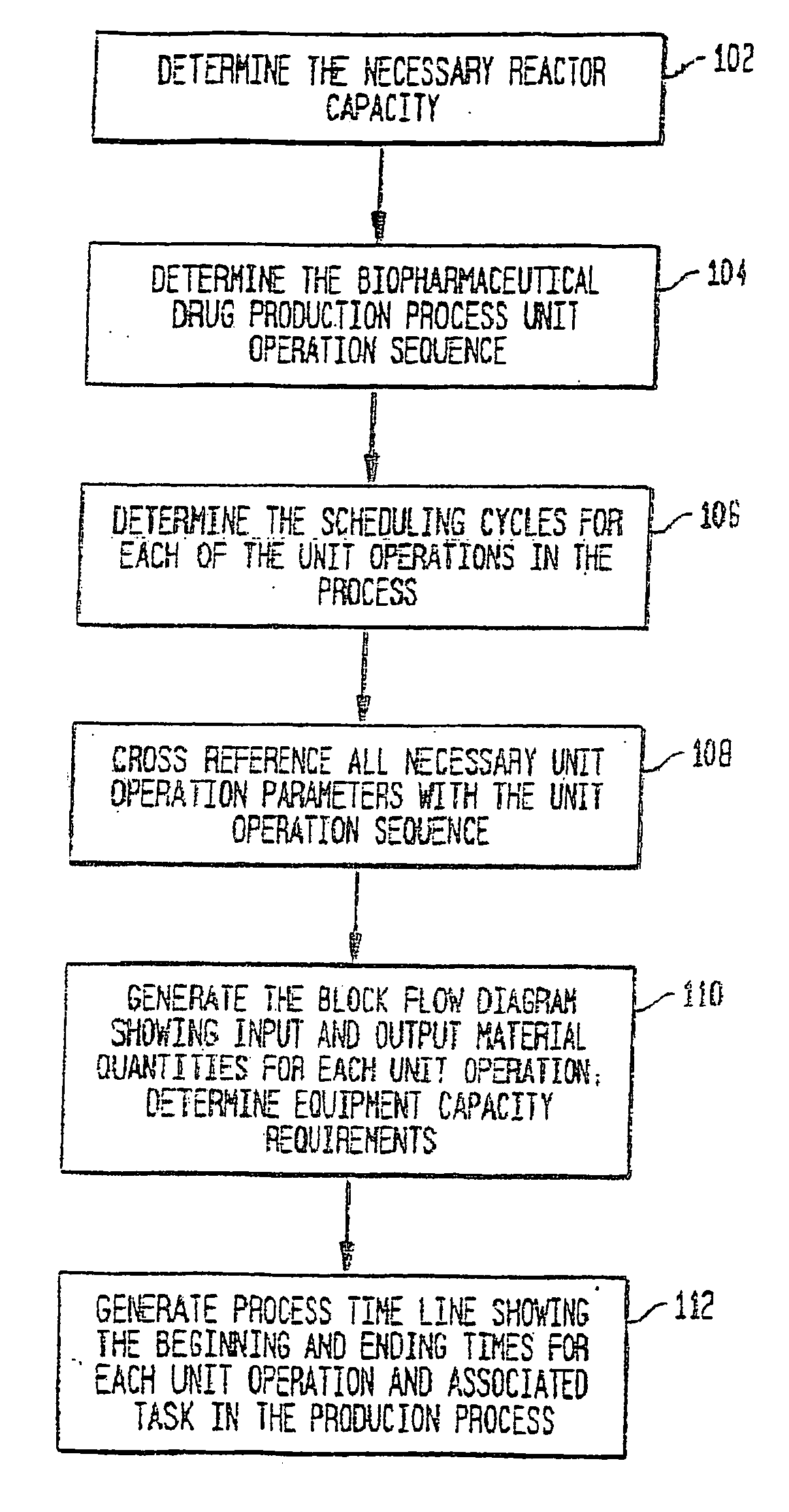
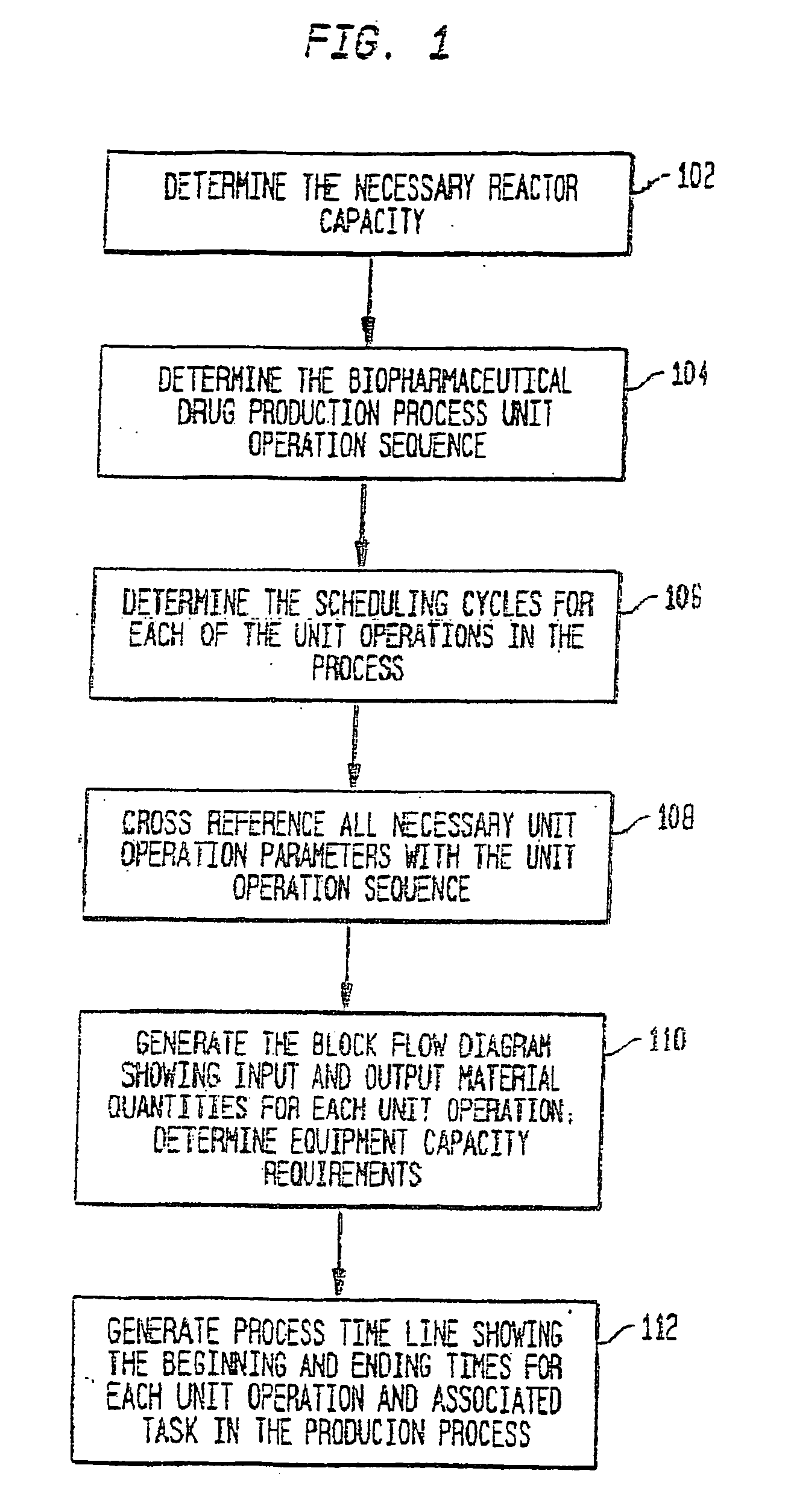
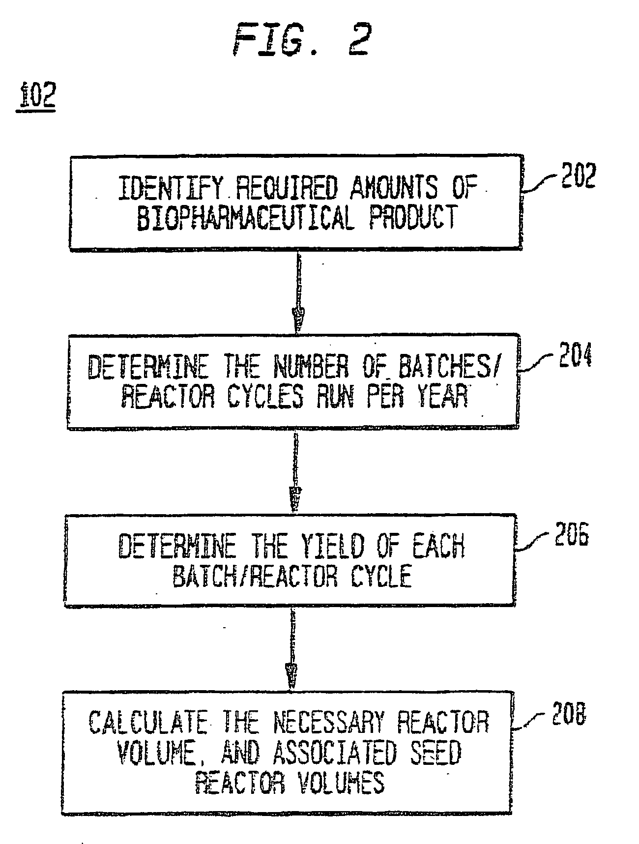
[0057] A system and method for the simulation and modeling of biopharmaceutical batch process manufacturing facilities using process time lines is described herein. The system employs an eleven-field delimited string code which specifies the unit identifier code and the iteration value for each of the ten levels of nested scheduling cycles—“Unit Operation Cycle-Sub Cycles,”“Unit Operation Cycles—Main Cycle,”“Unit Operation Cluster Cycle—Level 1—Sub Cycles,”“Unit Operation Cluster Cycle—Level 1—Main Cycle,”“Unit Operation Cluster Cycle—Level 2—Sub Cycle,”“Unit Operation Cluster Cycle—Level 2—Main Cycle,”“Unit Operation Cluster Cycle—Level 3—Sub Cycle,”“Unit Operation Cluster Cycle—Level 3—Main Cycle,” and “Batch Cycles” and “Lot Cycles”—of the biopharmaceutical drug production process being modeled. The method includes the step of selecting a sequence of unit operations wherein each of the sequence of unit operat...


PUM


Abstract

A system and method for the simulation and modeling of biopharmaceutical batch process manufacturing facilities using process time lines is described herein. The system employs an eleven-field delimited string code which specifies the unit identifier code and the iteration value for each of the ten levels of nested scheduling cycles of the biopharmaceutical drug production process being modeled. The method includes generating a process time line using operational parameters, a block flow diagram, and a set of scheduling cycles for each of a sequence of unit operations. The process time line is used as a tool for batch processing and facility design.

Description

RELATED APPLICATIONS [0001] This application claims the benefit of U.S. Provisional Application No. 60 / 572,305, filed on May 17, 2004, and U.S. Provisional Application No. 60 / 573,033, filed on May 19, 2004. This application is also related to U.S. patent application Ser. No. 10 / 822,229, filed Apr. 9, 2004, which claims the benefit of U.S. Provisional Patent Application No. 60 / 461,387, filed on Apr. 9, 2003. [0002] This patent application is also related to U.S. patent application Ser. No. 10 / 700,234, filed on Nov. 4, 2003, which is a continuation of U.S. patent application Ser. No. 09 / 373,794, filed on Aug. 13, 1999, now U.S. Pat. No. 6,662,061, issued on Dec. 9, 2003, which is a continuation-in-part of U.S. patent application Ser. No. 09 / 019,777, filed on Feb. 6, 1998, now U.S. Pat. No. 6,311,095, issued on Oct. 30, 2001, which claims the benefit of U.S. Provisional Patent Application No. 60 / 037,387, filed on Feb. 7, 1997; and is also related to U.S. patent application Ser. No. 10 / ...

Claims


Application Information

Patent Timeline
IPC IPC(8): G06F19/00
CPCG06Q10/04G06Q50/04Y02P90/30
Inventor BROWN, PETER G.
Owner APPLIED PROCESS TECH
Why Eureka
Try Eureka