Parallel flow evaporator with variable channel insertion depth

a technology of evaporator and channel, applied in the direction of indirect heat exchanger, refrigeration components, lighting and heating apparatus, etc., can solve the problems of heat exchanger orientation, significant evaporator and overall system performance degradation, and possible misdistribution of refrigeran

Inactive Publication Date: 2006-05-18
CARRIER CORP
View PDF19 Cites 41 Cited by
  • Summary
  • Abstract
  • Description
  • Claims
  • Application Information

AI Technical Summary

Benefits of technology

[0008] Briefly, in accordance with one aspect of the invention, the insertion depth of the individual parallel channels into the inlet manifold is varied so as to obtain a more uniform refrigerant distribution

Problems solved by technology

It causes significant evaporator and overall system performance degradation over a wide range of operating conditions.
Maldistribution of refrigerant may occur due to differences in flow impedances within evaporator channels, non-uniform airflow distribution over external heat transfer surfaces improper heat exchanger orientation or poor manifold and distribution system design.
Attempts to eliminate or reduce the effects of this phenomenon on the performance of parallel flow evaporators have been made with little or no success.
The primary reasons for such failures have generally been related to complexity and inefficiency of the proposed technique or prohibitively high cost of the solution.
The evaporator applications, although promising greater benefits and rewards, are more challenging and problematic.
Refrigerant maldistribution is one of the primary concerns and obstacles for the implementation of this technology in the evaporator applications.
As known, refrigerant maldistribution in parallel flow

Method used


Image

  • Parallel flow evaporator with variable channel insertion depth
  • Parallel flow evaporator with variable channel insertion depth
  • Parallel flow evaporator with variable channel insertion depth

Examples


Embodiment Construction

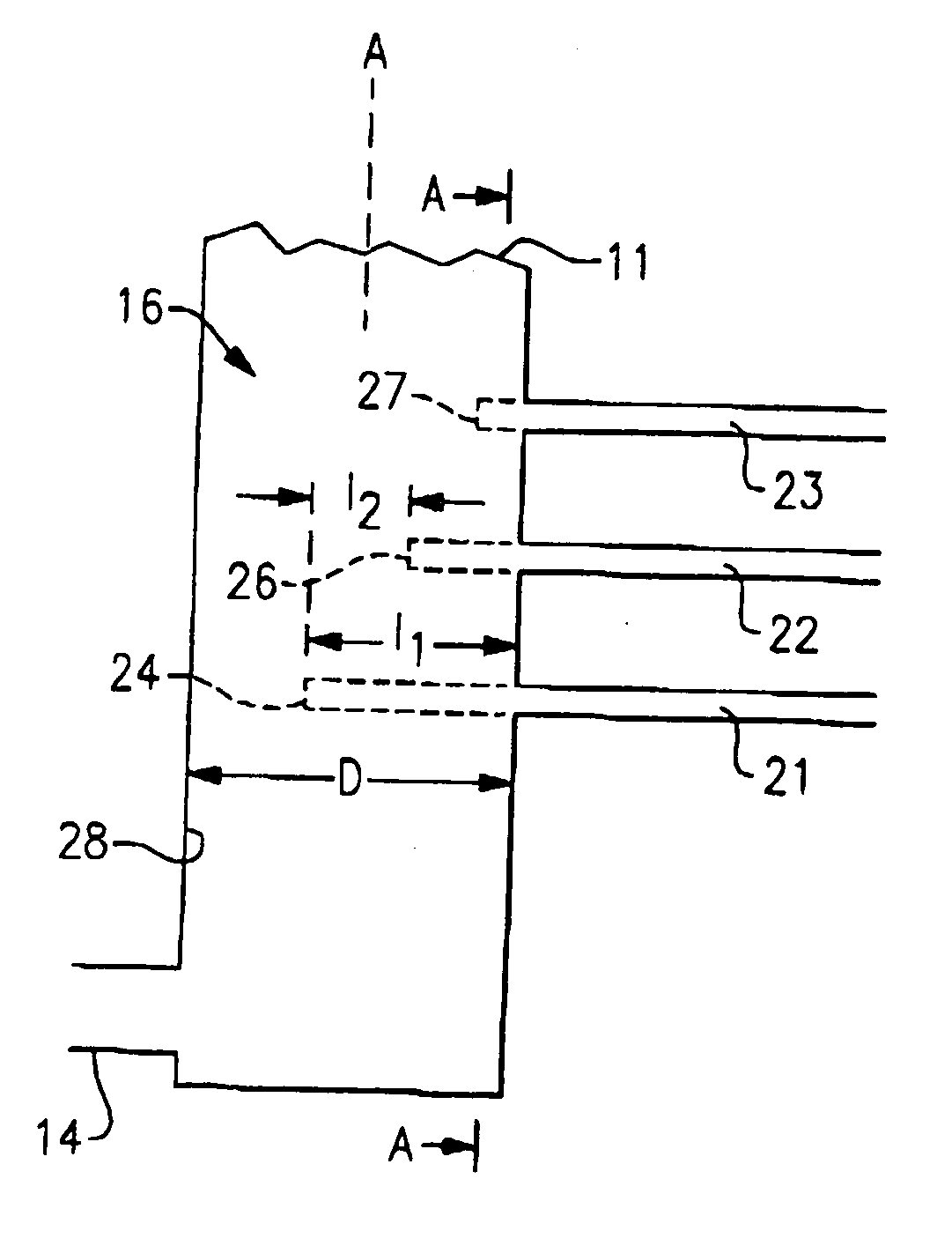
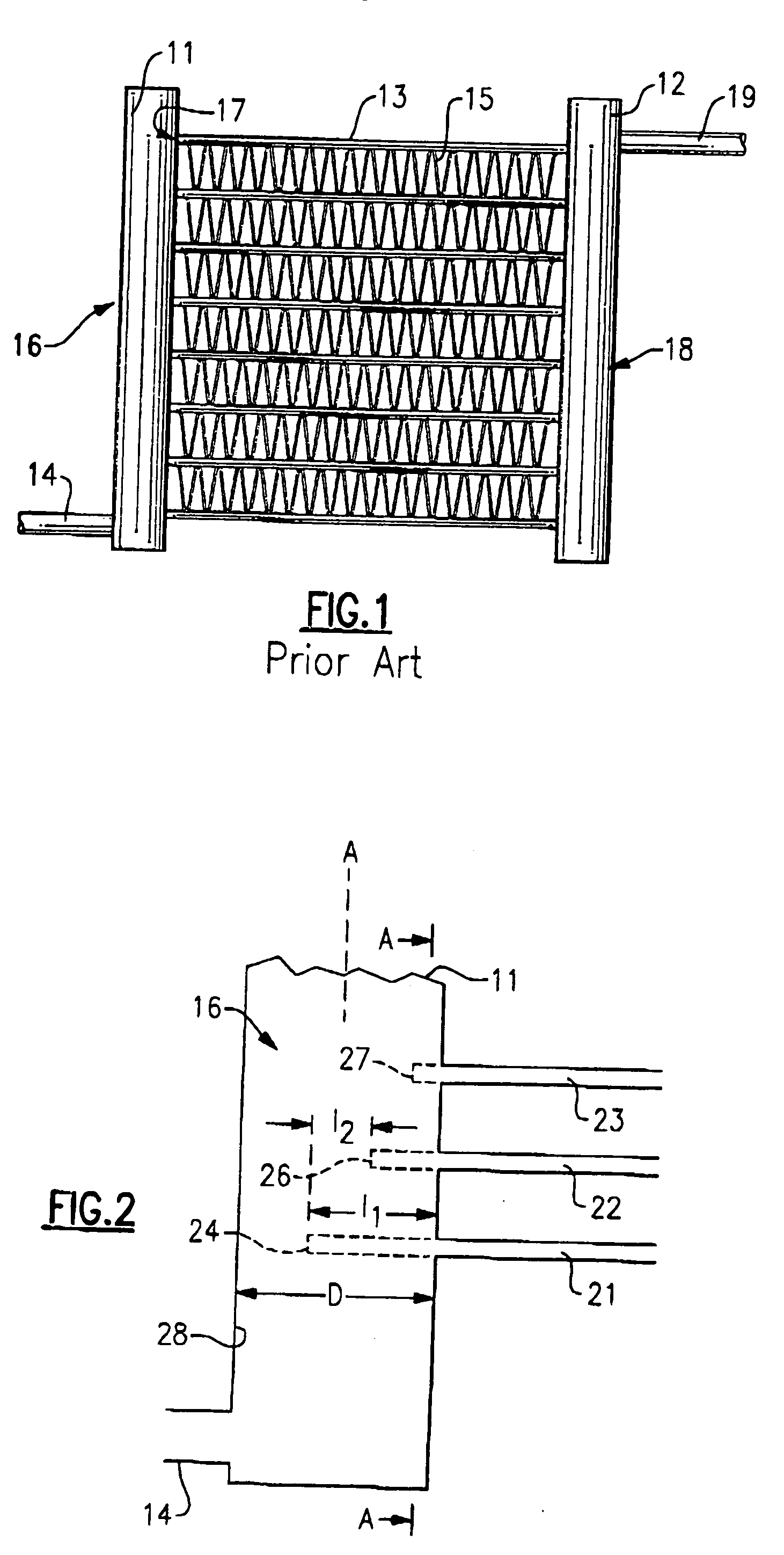
[0017] Referring now to FIG. 1, a parallel flow heat exchanger is shown to include an inlet header or manifold 11, an outlet header or manifold 12 and a plurality of parallel disposed channels 13 fluidly interconnecting the inlet manifold 11 to the outlet manifold 12. Generally, the inlet and outlet manifolds 11 and 12 are cylindrical in shape, and the channels 13 are usually tubes (or extrusions) of flattened or round shape. Channels 13 normally have a plurality of internal and external heat transfer enhancement elements, such as fins. For instance, external fins, disposed therebetween for the enhancement of the heat exchange process and structural rigidity, are typically furnace-brazed. Channels 13 may have internal heat transfer enhancements and structural elements as well.

[0018] The usual manner of attaching the parallel channels 13 to the inlet manifold 11 and the outlet manifold 12 is to insert the channels 13 so that they extend into the internal cavities of the inlet and ou...


PUM


Abstract

In a parallel flow heat exchanger having an inlet manifold connected to a plurality of parallel channels, the degree of insertion depth of the parallel channels into the inlet manifold is variable so as to adjust the impedance to the refrigerant flow into the individual channels. The degree of insertion depth is progressively reduced toward a downstream end of the manifold for the individual channels or for the channel sections. The diameter of the inlet manifold is locally increased or its cross-section area altered in order to accommodate the flow of refrigerant around the tube insertions. Similar technique is applied to the outlet manifold as well to further balance hydraulic resistances.

Description

BACKGROUND OF THE INVENTION [0001] This invention relates generally to air conditioning and refrigeration systems and, more particularly, to parallel flow evaporators thereof. [0002] A definition of a so-called parallel flow heat exchanger is widely used in the air conditioning and refrigeration industry now and designates a heat exchanger with a plurality of parallel passages, among which refrigerant is distributed and flown in the orientation generally substantially perpendicular to the refrigerant flow direction in the inlet and outlet manifolds. This definition is well adapted within the technical community and will be used throughout the text. [0003] Refrigerant maldistribution in refrigerant system evaporators is a well-known phenomenon. It causes significant evaporator and overall system performance degradation over a wide range of operating conditions. Maldistribution of refrigerant may occur due to differences in flow impedances within evaporator channels, non-uniform airfl...

Claims


Application Information

Patent Timeline
IPC IPC(8): F28F9/02F25B39/02
CPCF25B39/00F25B2500/01F28D1/05383F28D2021/0071F28F9/02F28F9/0282
Inventor TARAS, MICHAEL F.KIRKWOOD, ALLEN C.CHOPKO, ROBERT A.
Owner CARRIER CORP
Why Eureka
Try Eureka