
Electronic fence capable of guiding animals to return

a technology of electric fences and fences, applied in the field of electric fences, can solve problems such as inefficiency, electric shock generation, and animal running away

Inactive Publication Date: 2006-05-18
DTSYST
View PDF28 Cites 39 Cited by
  • Summary
  • Abstract
  • Description
  • Claims
  • Application Information

AI Technical Summary

Benefits of technology

[0011] Accordingly, the present invention has been made to solve the above problems occurring in the prior art, and it is an object of the present invention is to provide an electronic fence capable of guiding animals under training to return to a predetermined restricted area, which automatically controls an electric shock level in response to the location of the restricted area when the animals attempt to escape from the restricted area to efficiently control the animals and judges correct positions of the animals so as not to generate electrical shock when the animals return to the restricted area.

Problems solved by technology

However, the aforementioned electronic fence generates an electric shock having a constant level when the animal escapes from a restricted area, and thus it is not efficient.
Furthermore, the electric shock is generated even when the escaped animal return to the restricted area.
Thus, the animal cannot enter the electronic fence due to the electric shock so that the animal may run away.
If an electric shock is given to the animals when they are returning to the restricted area, the animals run away so that they can be lost.
Moreover, the runaway animals may die from car accidents in many cases.
Furthermore, the conventional electronic fence cannot detect the moving directions of the animals when the animals escape from the restricted area.

Method used


Image

  • Electronic fence capable of guiding animals to return
  • Electronic fence capable of guiding animals to return
  • Electronic fence capable of guiding animals to return

Examples


Embodiment Construction

[0021] Reference will now be made in detail to the preferred embodiments of the present invention, examples of which are illustrated in the accompanying drawings.

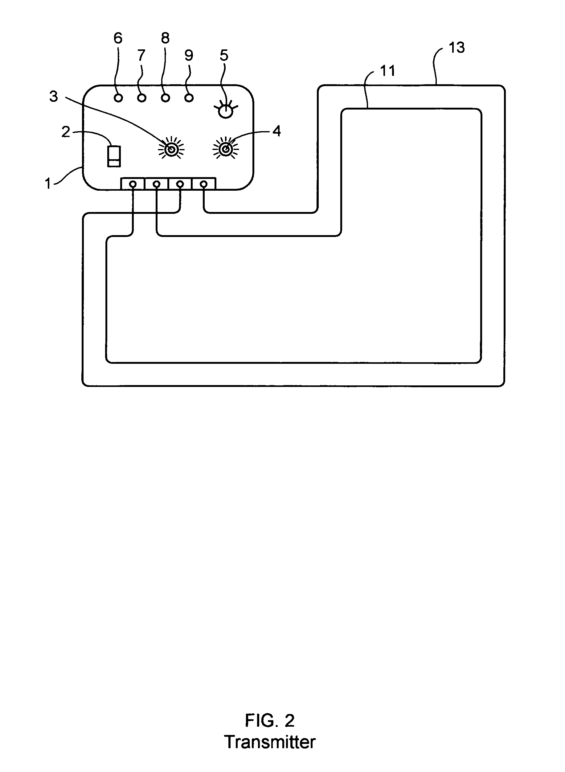
[0022]FIG. 2 illustrates a transmitter 1 of an electronic fence according to the present invention, and FIG. 4 is a block diagram of the transmitter 1 of the electronic fence according to the present invention. The transmitter 1 transmits radio signals having different frequency bands such that different shock waves are generated in response to positions of an animal moving close to the boundary of a predetermined restricted area. In addition, the transmitter 1 generates a control signal for indicating a selected function.

[0023] Referring to FIGS. 2 and 4, the electronic fence of the present invention includes a power switch 2, an AC-DC converter 10, a function selection switch 5, an electric shock level control lever 4, a transmitter power level control lever 3, a frequency output circuit 17, a microprocessor 16, an ante...


PUM


Abstract

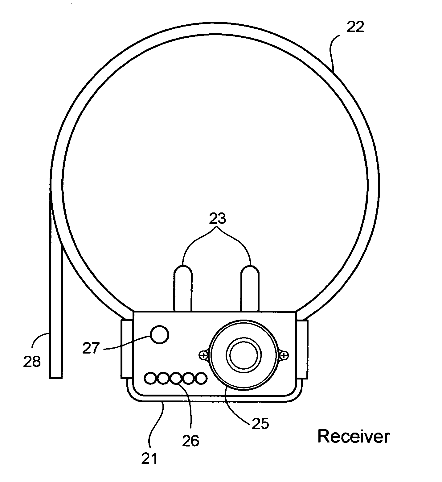
An electronic fence system capable of guiding animals under training to return to a predetermined restricted area. The electronic fence generates electric shocks as the animals attempt to leave the predetermined restricted area and restrains the electrical shock when the animals return to the predetermined restricted area. The electronic fence includes a transmitter and a receiver. The transmitter transmits RF signals having a plurality of control signals such that different shock levels are generated responsive to the location of the animals within the predetermined restricted area. The receiver sets a shock wave level, selectively controls the generation of the electric shock and a high-frequency beep, automatically restrains the generation of the electric shock when an escaped animal returns to the predetermined restricted area, and generates an audible alarm and turns lamps on and off to indicate the location of the animal when it escapes from the predefined restricted area.

Description

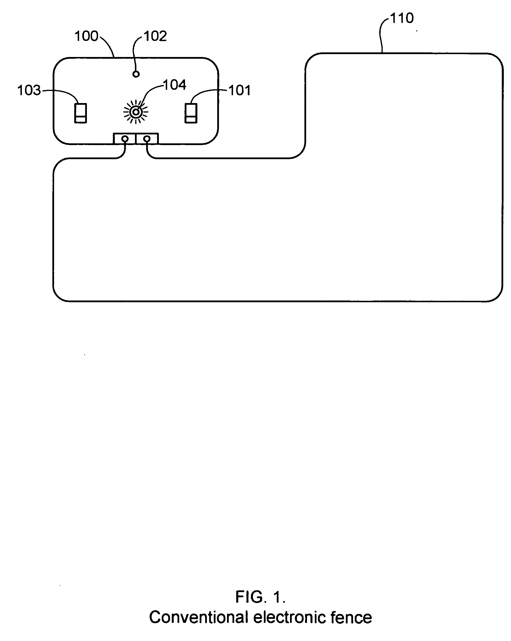
BACKGROUND OF THE INVENTION [0001] 1. Field of the Invention [0002] The present invention relates to an electronic fence, and more particularly, to an electronic fence capable of guiding animals under training to return to a predetermined restricted area, which automatically controls an electric shock level in response to the location of the restricted area when the animals attempt to escape from the restricted area to efficiently control the animals and judges correct positions of the animals so as not to generate an electrical shock when the animals are returned to the restricted area. [0003] 2. Background of the Related Art [0004]FIG. 1 shows a conventional electronic fence. In FIG. 1, reference numeral 100 denotes a transmitter connected to a transmission wire antenna 110 for transmitting an electric wave. The transmitter 100 includes an electric shock level control lever 101 for setting the level of a shock wave to be applied to animals, an antenna checking lamp 102, a power sw...

Claims


Application Information

Patent Timeline
IPC IPC(8): A01K15/02
CPCA01K15/023A01K3/005A01K15/04A01K15/029
Inventor KIM, JOON S.
Owner DTSYST
Learn More