
Fuel cell equipped vehicle

Inactive Publication Date: 2006-05-18
TOYOTA JIDOSHA KK
View PDF14 Cites 63 Cited by
  • Summary
  • Abstract
  • Description
  • Claims
  • Application Information

AI Technical Summary

Benefits of technology

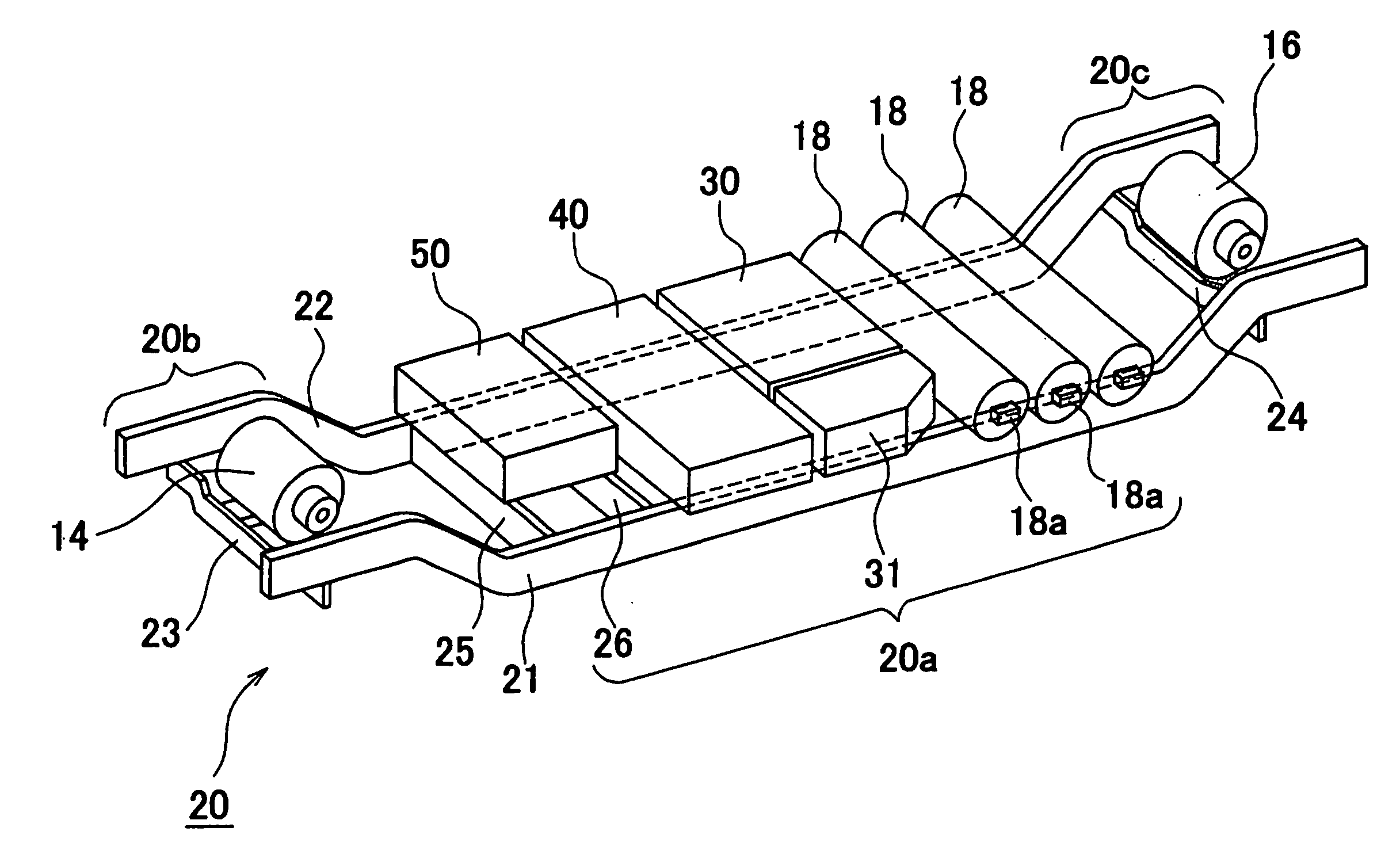
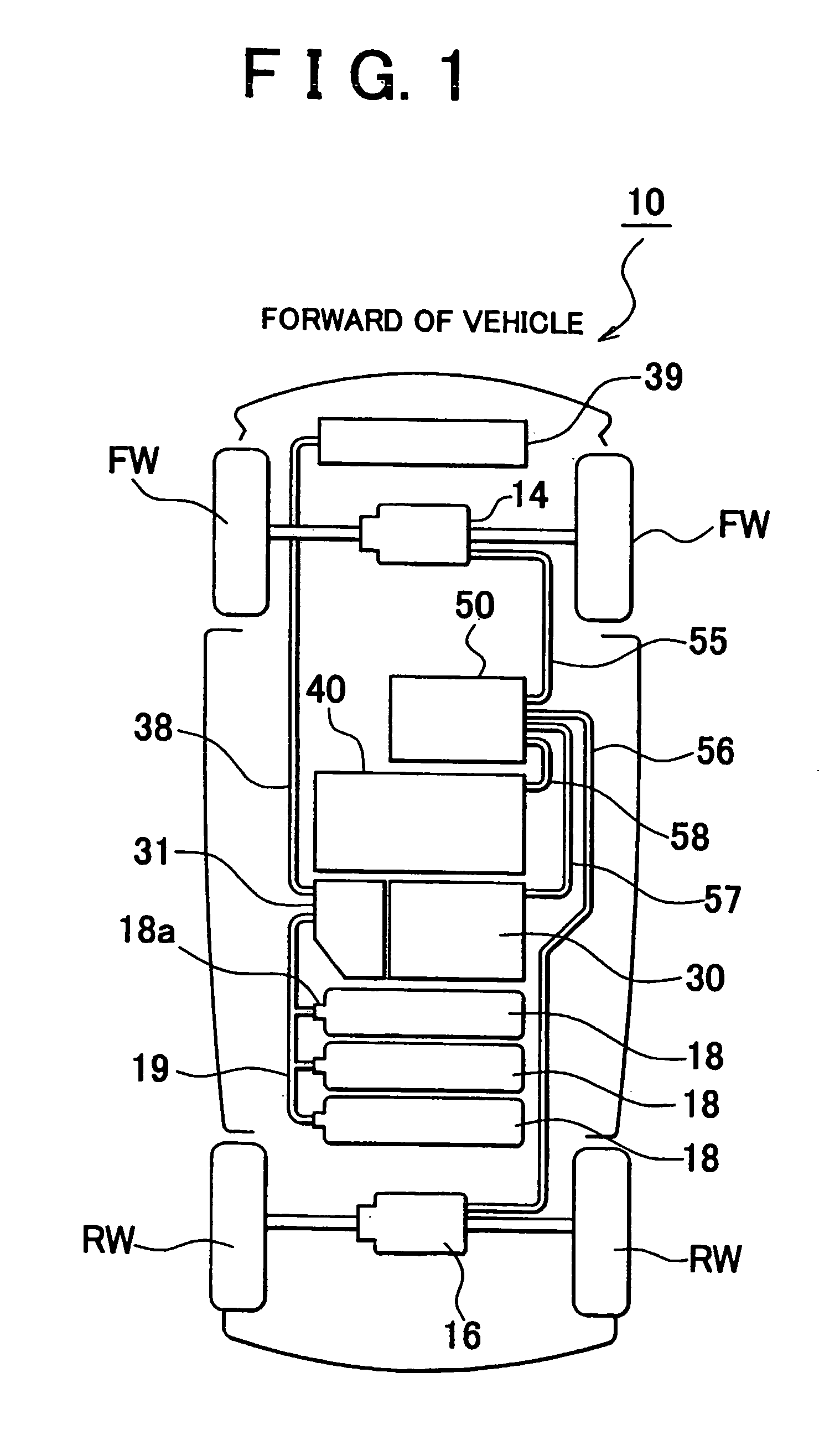
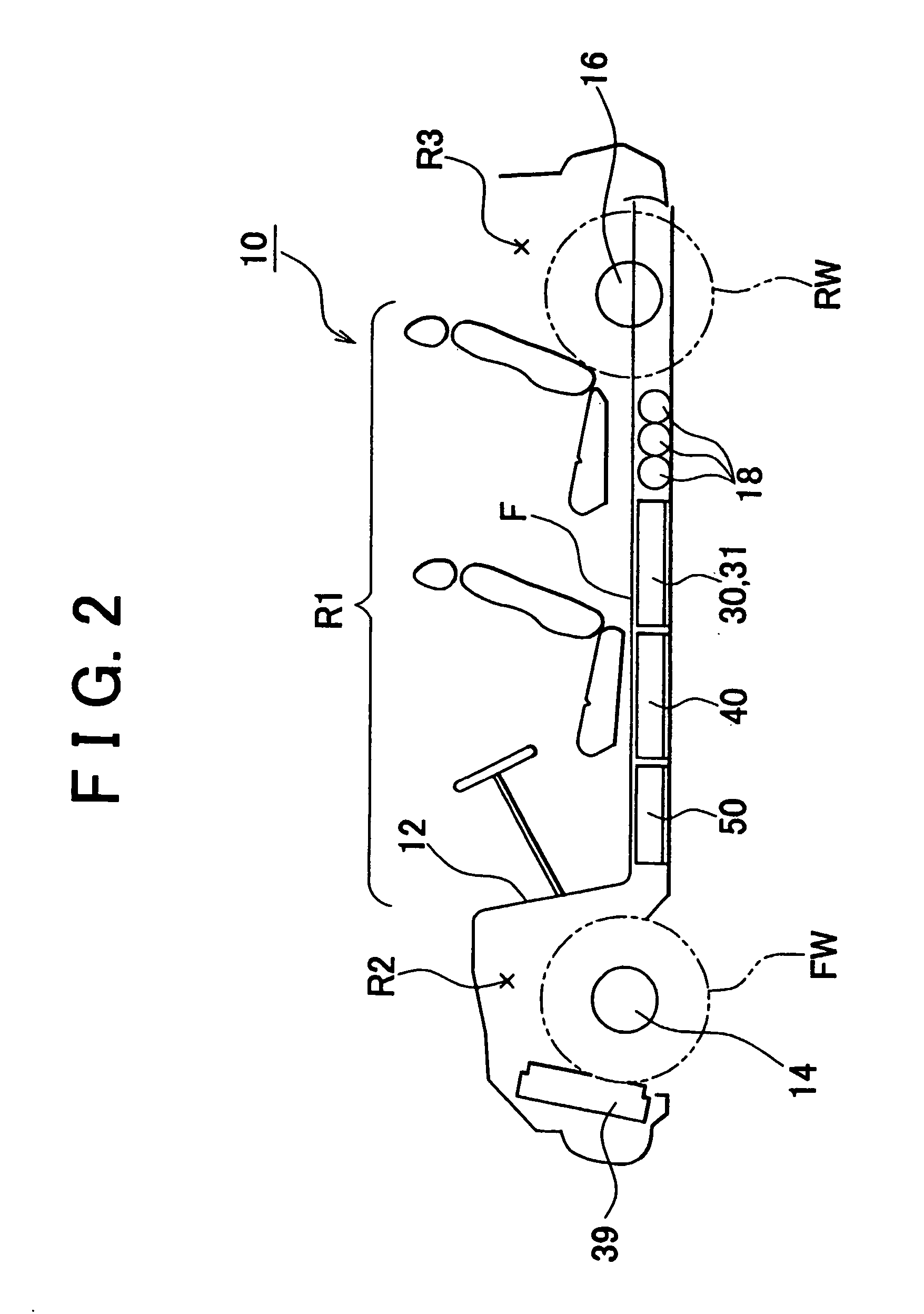
[0006] In the above-described fuel cell equipped vehicle of the invention, major component devices, such as the fuel cell, the fuel gas tank, the fuel cell accessory, the storage battery, and the electric power control unit, are disposed below the floor of the passenger compartment in a concentrated fashion. Therefore, the major component devices do not reduce the space of a compartment of the vehicle (e.g., a forward compartment, a passenger compartment, and a rearward compartment). Furthermore, since the component devices disposed below the floor of the passenger compartment have relatively great weights, the center of gravity of the vehicle comes to a low position near the center of the vehicle, thus achieving good running stability of the vehicle.
[0015] In a preferred form of the above-described fuel cell equipped vehicle, the radiator may be disposed so as to lie between two frame rails of the body frame. This arrangement will increase the space of the forward compartment of the vehicle.

Problems solved by technology

However, Japanese Patent Application Laid-open No. 2001-268720 does not consider where to dispose an electric power control device (also referred to as “power control unit”) that drives a vehicle-driving motor using electric power from the fuel cell battery or electric power from a storage battery, and charges the storage battery using power from the fuel cell battery.
Therefore, if the electric power control device is disposed within a compartment of the vehicle, there occur problems.
For example, the compartment space of the vehicle is reduced, and the center of gravity of the vehicle cannot be sufficiently lowered.

Method used


Image

  • Fuel cell equipped vehicle
  • Fuel cell equipped vehicle
  • Fuel cell equipped vehicle

Examples


Embodiment Construction

[0023] To make the invention more apparent and clear, preferred embodiments of the invention will be described with reference to the accompanying drawings. FIG. 1 is a schematic plan view of a fuel cell equipped vehicle in accordance with an embodiment of the invention. FIG. 2 is a schematic sectional view of the fuel cell equipped vehicle. FIG. 3 is a perspective view of various component devices arranged on a body frame. FIG. 4 is a block diagram of the fuel cell equipped vehicle.

[0024] A fuel cell equipped vehicle 10 of the embodiment, as shown in FIG. 2, has a passenger compartment R1 in which a driver seat, a passenger or navigator seat and rear seats are disposed, a forward compartment R2 provided near front wheels and separated from the passenger compartment R1 by a dashboard 12, and a rearward compartment R3 provided near rear wheels for use as a luggage compartment or the like.

[0025] The fuel cell equipped vehicle 10 has a body frame 20 as shown in FIG. 3. The body frame ...


PUM


Abstract

In a fuel cell equipped vehicle (10), hydrogen cylinders (18) storing hydrogen gas to be supplied to a fuel cell battery (30), a fuel cell (30), fuel cell accessories (31), a storage battery (40), and a PCU (50) that controls the supply of electric power from the fuel cell (30) and the storage battery (40) to a front wheels-driving electric motor (14) and a rear wheels-driving electric motor (16) are arranged in that order under a floor of a passenger compartment (R1). Therefore, these major component devices do not reduce the spaces of a passenger compartment (R1), a forward compartment (R2), and a rearward compartment (R3). Since the component devices disposed under the floor of the passenger compartment (R1) have relatively great weights, the center of gravity of the vehicle comes to a low position in a central portion of the vehicle, thus achieving good running stability of the vehicle.

Description

FIELD OF THE INVENTION [0001] The invention relates to a fuel cell equipped vehicle. BACKGROUND OF THE INVENTION [0002] Various fuel cell equipped vehicles in which fuel cells are disposed so that a reduction of the compartment space is avoided or minimized have been proposed. For example, Japanese Patent Application Laid-open No. 2001-268720 proposes a vehicle in which a fuel cell battery, a hydrogen storage alloy tank, fuel cell accessories, and a battery unit are horizontally arranged immediately under a compartment floor between the front and rear wheels. [0003] However, Japanese Patent Application Laid-open No. 2001-268720 does not consider where to dispose an electric power control device (also referred to as “power control unit”) that drives a vehicle-driving motor using electric power from the fuel cell battery or electric power from a storage battery, and charges the storage battery using power from the fuel cell battery. Therefore, if the electric power control device is d...

Claims


Application Information

Patent Timeline
IPC IPC(8): B60L8/00B60K1/02B60K1/04B60K11/04B60K15/03B60K15/063B60L11/18H01M8/00H01M8/04H01M16/00
CPCB60K1/02B60K1/04B60K11/04B60K15/063B60K2001/005B60L11/1881B60L2200/26B60L11/1894H01M16/006H01M2250/20Y02T90/32Y02T90/34B60L11/1892B60L2220/42B60L2260/28B60L50/66B60L58/40B60L58/33B60L58/34B60L50/71Y02T10/64Y02T10/70Y02T90/40Y02T10/7072Y02E60/50Y02E60/10B60L50/72B60L50/64B60K7/0007B60K15/03006B60K15/07B60K2015/03315
Inventor MIZUNO, MINOBU
Owner TOYOTA JIDOSHA KK
Learn More