High voltage ciruit breaker with cooling

a high-voltage ciruit breaker and cooling technology, which is applied in the direction of insulated conductors, power cables, cables, etc., can solve the problems of exceeding the maximum permissible temperature limit values of circuit breaker, and achieve efficient cooling, low cost, and dissipate only a very small amount of heat

Active Publication Date: 2006-05-18
HITACHI ENERGY SWITZERLAND AG
View PDF9 Cites 25 Cited by
  • Summary
  • Abstract
  • Description
  • Claims
  • Application Information

AI Technical Summary

Benefits of technology

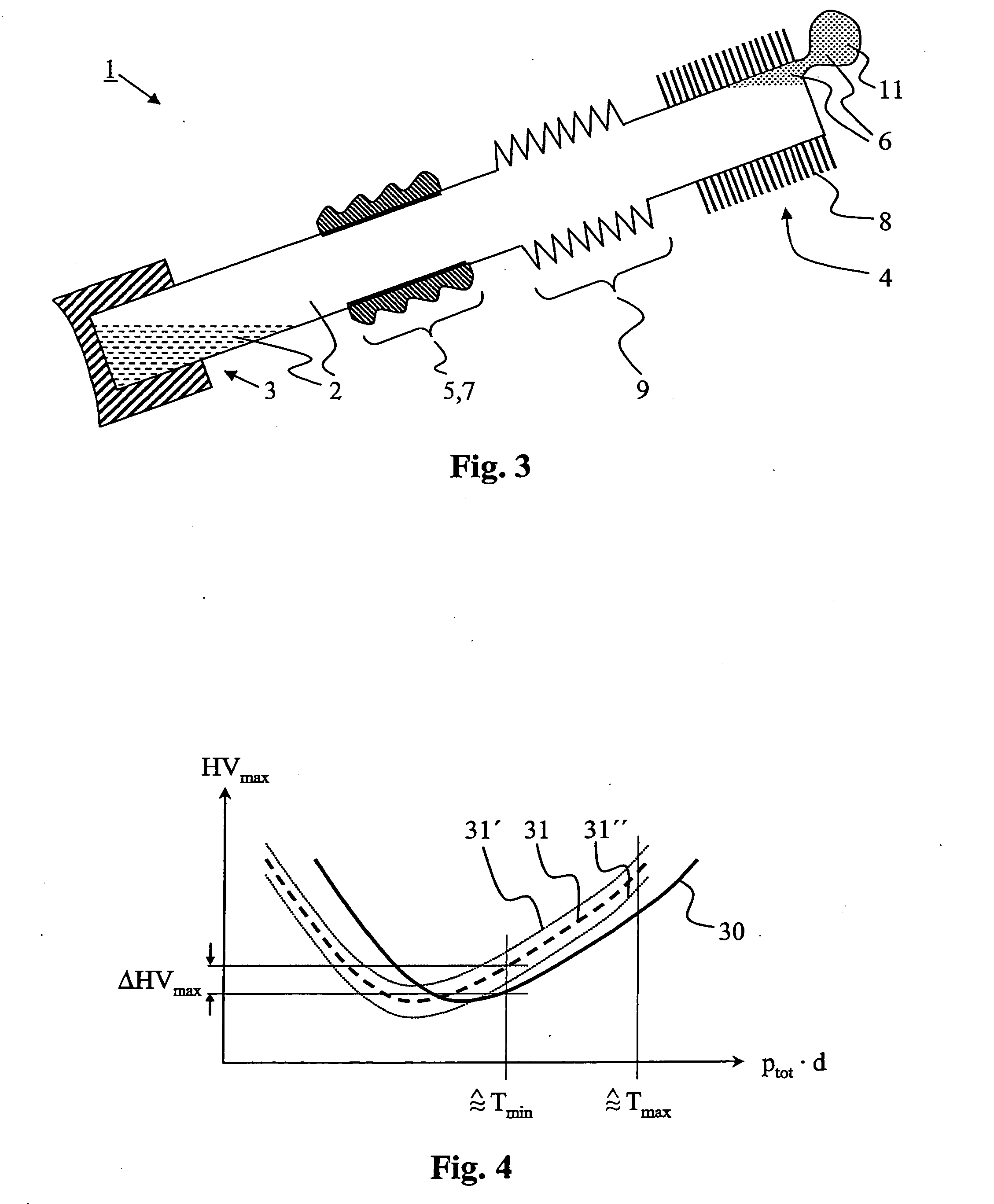
[0026] The auxiliary gas which, for example, is at a partial pressure in the order of magnitude of 100 mbar to 500 mbar in the heat pipe allows a minimum pressure to be ensured even at low temperatures, and thus a corresponding dielectric strength in the heat pipe. The working liquid does not start to boil until that temperature at which its vapor pressure exceeds the auxiliary gas pressure.
[0027] In conjunction with the Paschen curve, this corresponds to a shift in the curve, and thus in the breakdown voltage minimum (as well) to the left, that is to say to low values of the (total) pressure times the insulating gap length. If the insulating gap length is constant, the circuit breaker can thus either have higher voltages applied to it by the provision of the (not infinitely low) partial pressure of auxiliary gas for the same temperature range Tmin to Tmax of the circuit breaker or, if the circuit breaker is designed for the same high voltages, can be used for a wider temperature range (with a lower Tmin). Alternatively, a shorter insulating gap length can be provided for the same temperature range and the same voltages.
[0028] The auxiliary gas is advantageously gaseous over the entire temperature range Tmin to Tmax. The auxiliary gas can thus dissipate only a very small amount of heat, and it is moved by the vaporizing working medium in the direction of the condenser. It is thus advantageously possible to provide an auxiliary gas holding volume at the condenser, which is essentially filled with the majority of the auxiliary gas, or with all of the auxiliary gas in operating conditions. This makes it possible to prevent the area which is available to the working medium for condensation from not being blocked or being blocked only to a minor extent by the auxiliary gas. Efficient cooling is achieved. The auxiliary gas holding volume may be rigid (constant volume content). The volume content of the auxiliary gas holding volume is advantageously variable, and increases with the temperature and the internal pressure in the heat pipe. An auxiliary gas holding volume such as this is advantageously designed to be deformable (for example in the form of a bellows) and, for example, is formed from a deformable material.
[0029] The partial pressure of the auxiliary gas is advantageously chosen such that, in operating conditions (typically at Tmax), the (total) internal pressure of the heat pipe corresponds to the external pressure (just) surrounding the heat pipe, that is to say typically being about 1 bar (1000 mbar plus / minus 100 mbar to 250 mbar) or advantageously virtually 1 bar. It is also possible to provide lower or, advantageously, higher pressures within the heat pipe. Two or more bar or else a plurality of tens of bar, for example using ammonium as the working medium, can, for example, make up for the necessary design complexity (pressure sealing) by making it possible to provide a shorter insulating gap.
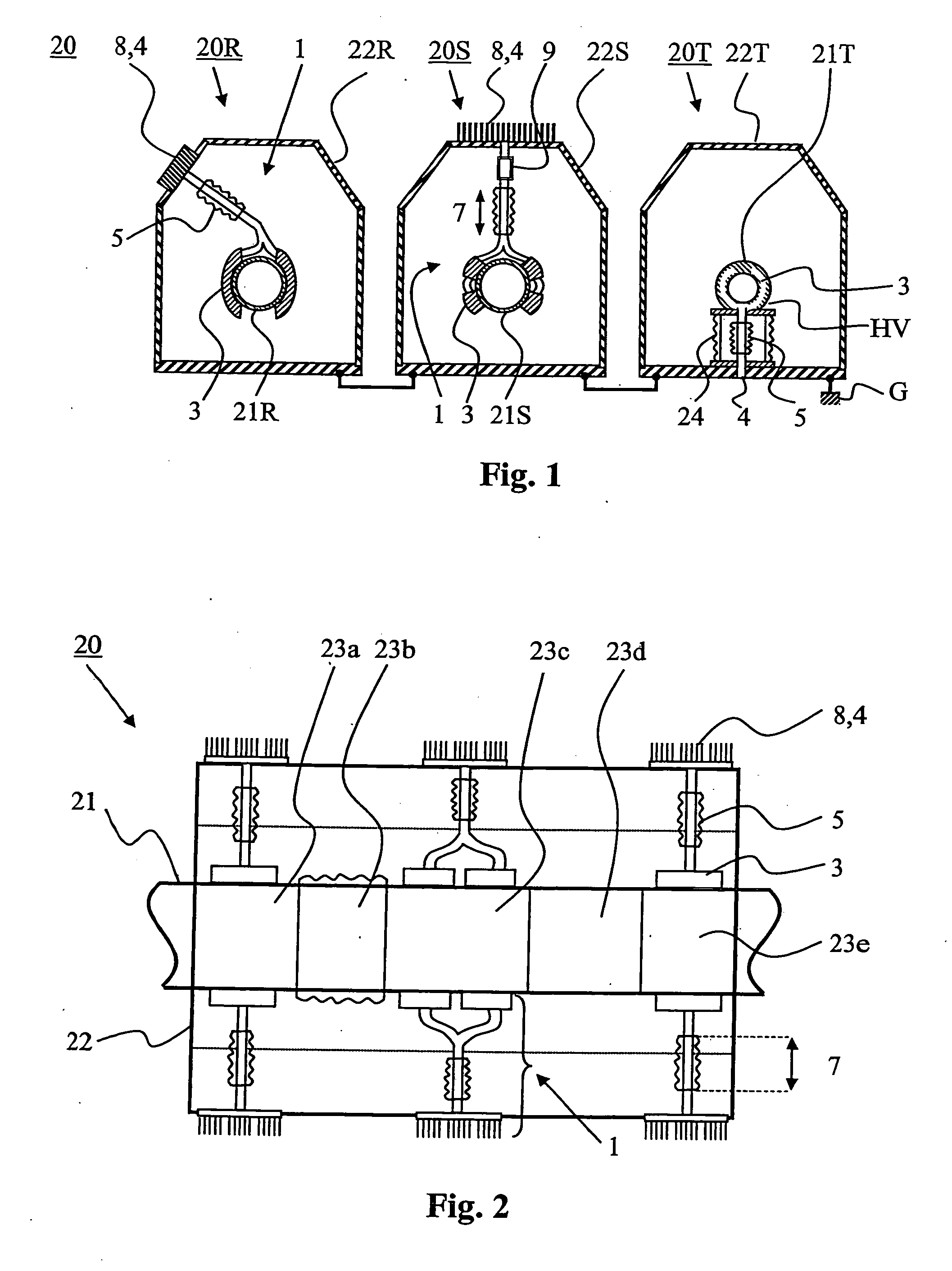
[0030] The inner conductor can advantageously have a plurality of sections which are each provided with at least one heat pipe. Particularly in the case of very long circuit breakers with long inner conductors, very efficient cooling is possible by associating in each case at least one heat pipe with a plurality of sections of the circuit breaker, which are arranged one behind the other in the longitudinal direction, along the longitudinal extent of the inner conductor.

Problems solved by technology

An arrangement such as this has the disadvantage that it is active, that is to say it must be driven.
A failure, for example of the power supply to the fans, leads to failure of the cooling and can quickly lead to the maximum permissible temperature limit values of the circuit breaker being exceeded.

Method used


Image

  • High voltage ciruit breaker with cooling
  • High voltage ciruit breaker with cooling
  • High voltage ciruit breaker with cooling

Examples


Embodiment Construction

[0004] One object of the invention is therefore to provide a circuit breaker and a method for cooling an inner conductor of a circuit breaker of the type mentioned initially, which do not have the disadvantages described above. One particular aim is to create a circuit breaker with a passive and (virtually) maintenance-free cooling system.

[0005] This object is achieved by an apparatus and a method having the features of the independent patent claims.

[0006] A circuit breaker whose inner conductor (which can also be referred to as the active part) is cooled can carry higher currents than an uncooled circuit breaker while complying with the temperature limit values specified by the relevant standards. The current carrying capacity of a circuit breaker can thus be increased to a greater extent the more efficiently a cooling apparatus which is provided can dissipate the heat losses which are produced on the inner conductor.

[0007] A circuit breaker according to the invention having an ...


PUM

PropertyMeasurementUnit
rated voltagesaaaaaaaaaa

Abstract

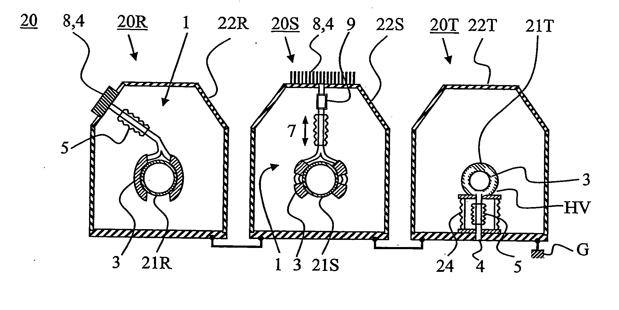
In order to dissipate heat losses from the inner conductor (21), the circuit breaker (20) having an elongated inner conductor (21) and an outer conductor (22) which surrounds the inner conductor (21) like a housing has at least one heat pipe (1) which extends from the inner conductor (21) to the outer conductor (22) and has an insulating hollow body (5) in order to form an electrical insulating gap (7). The heat pipe (1) advantageously has a flexibly deformable section (9). The heat pipe (1) can run in a supporting insulator (24) which supports the inner conductor (21). In addition to a working medium, the heat pipe (1) advantageously also contains an auxiliary gas which results in an enhanced dielectric strength at low temperatures.

Description

TECHNICAL FIELD [0001] The invention relates to the field of circuit breaker technology. It relates to a circuit breaker and to a method for cooling an inner conductor of a circuit breaker as claimed in the precharacterizing clause of the independent patent claims. PRIOR ART [0002] A circuit breaker such as this and a method such as this are known, for example, from EP 1 022 830 A1. In this document, fans are provided for cooling an inner conductor, which is in a housing, of a circuit breaker, by means of which fans a circular flow is produced which flows around the inner conductor. The gas which is circulated in this way absorbs heat losses from the inner conductor and then emits these heat losses to the inner face of the housing. The housing in turn emits heat to the surrounding air outside the housing. The cooling of the inner conductor means that greater currents can be carried. [0003] An arrangement such as this has the disadvantage that it is active, that is to say it must be ...

Claims


Application Information

Patent Timeline
Patent Type & Authority Applications(United States)
IPC IPC(8): H05B3/02
CPCF28D15/02F28D15/04F28D15/06H02G5/10H01H9/52H01H2009/523H01H2009/526F28F21/062
Inventor LAKNER, MARTINCHARTOUNI, DANIELMAUROUX, JEAN-CLAUDESCHOENEMANN, THOMASKIEFER, JOCHENZEHNDER, LUKASMOLLENKOPF, MARC
Owner HITACHI ENERGY SWITZERLAND AG
Why Eureka
Try Eureka