Stator for outer rotor multipole generator and method of assembling the stator

a multi-pole generator and stator technology, applied in the manufacture of slip-rings, windings, dynamo-electric components, etc., can solve the problems of so-called loose wires and the long time-consuming stator assembly operation process, and achieve the effect of improving the efficiency of stator assembly

Inactive Publication Date: 2006-05-18
SAWAFUJI ELECTRIC COMPANY
View PDF8 Cites 17 Cited by
  • Summary
  • Abstract
  • Description
  • Claims
  • Application Information

AI Technical Summary

Benefits of technology

[0011] In accordance with the arrangement of the third aspect, by carrying out connecting by fusing by holding the lead wire from the coil between the connecting plate portion and the clamping plate portion while fitting and fixing the connecting terminal to the bobbin, it is unnecessary to carry out bending of a part of the connecting terminal after connecting by fusing, the lead wire does not flex between the coil and the part connected to

Problems solved by technology

Due to this bending of the coil connection terminal portion after connecting the lead wire by fusing, the lead wire flexes between the coil and a part where the lead wire is connected to the coil connection terminal portion, thus causing a so-called loose wire.
Furthermore, since it is necessary for a step of catching the lead wire with the connecting terminal when the connecting terminal is provisionally inser

Method used


Image

  • Stator for outer rotor multipole generator and method of assembling the stator
  • Stator for outer rotor multipole generator and method of assembling the stator
  • Stator for outer rotor multipole generator and method of assembling the stator

Examples


Embodiment Construction

[0021] Modes for carrying out the present invention are explained below with reference to embodiments of the present invention shown in the attached drawings.

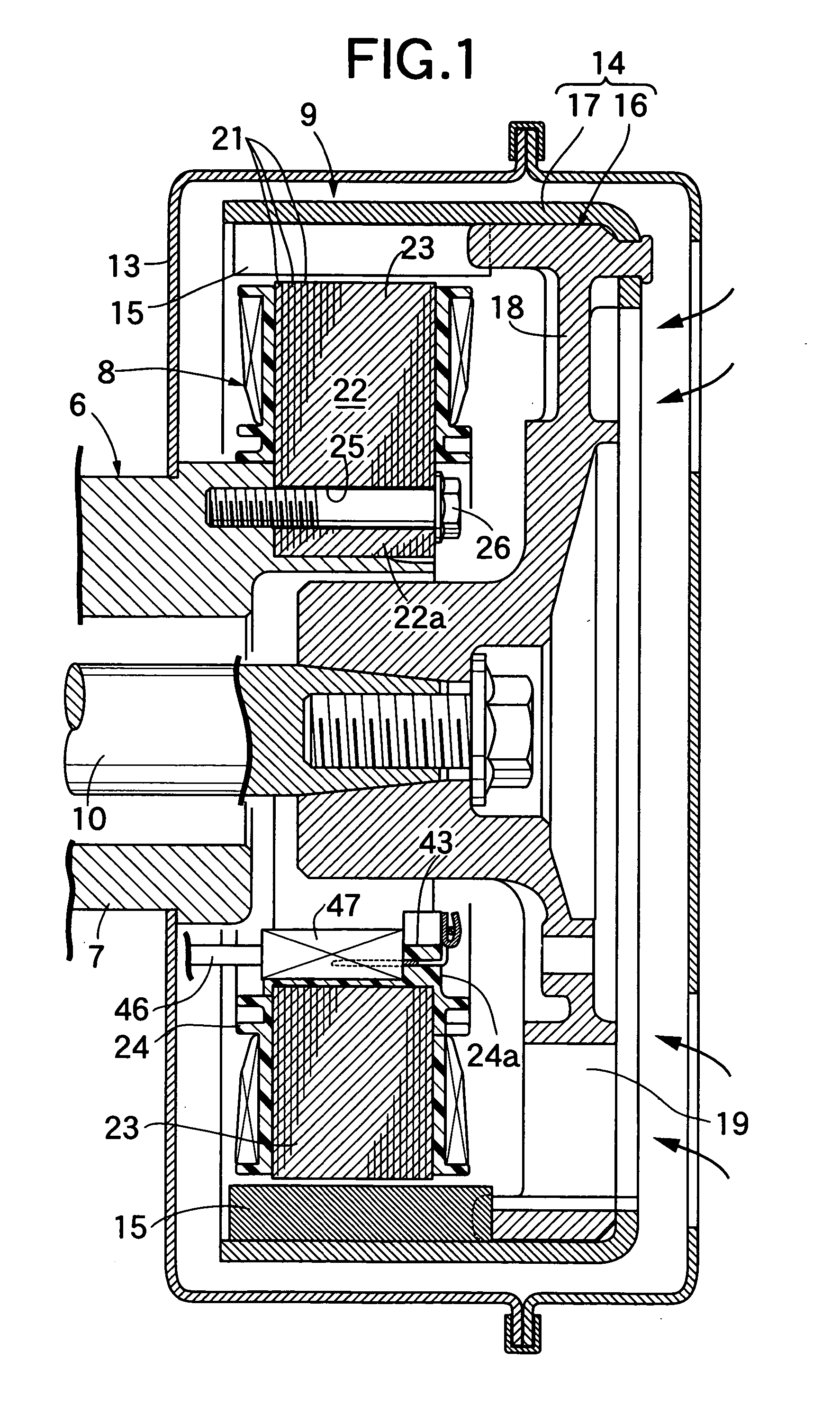
[0022] A first embodiment of the present invention is now explained with reference to FIG. 1 to FIG. 7; in FIG. 1, this outer rotor type multi-pole generator is used as, for example, an engine generator, and includes a stator 8 mounted on an engine main body 6 via a hollow support 7, and a rotor 9 covering the stator 8, the rotor 9 being fixed to an end of a crankshaft 10 running rotatably through the support 7 and arranged coaxially with the stator 8. Fixedly supported on the support 7 is a casing 13 covering the stator 8 and the rotor 9.

[0023] The rotor 9 is formed by fixedly attaching a plurality of magnets 15 to the inner periphery of a bottomed cylindrical rotor yoke 14 coaxially covering the stator 8, and a central part of a closed end of the rotor yoke 14 is fixed coaxially to the end of the crankshaft 10.

[0024] The r...


PUM

PropertyMeasurementUnit
Poweraaaaaaaaaa
Electric potential / voltageaaaaaaaaaa
Widthaaaaaaaaaa

Abstract

An outer rotor type multi-pole generator stator is provided in which a lead wire extending from a coil is connected by fusing to a connecting terminal fitted into and fixed to a bobbin wherein, in order to avoid the lead wire becoming slack after connection by fusing and enable assembly of the stator to be carried out efficiently, the connecting terminal (32) is formed from an external conductor connection terminal portion (32a) that is fitted into and fixed to a fitting hole (31), a connecting plate portion (32b) having one end thereof connected at right angles to the external conductor connection terminal portion (32a) and extending toward the radially inner side of the stator, and a clamping plate portion (32c) provided so as to be connected to the connecting plate portion (32b) so that the lead wire (33) can be held between the clamping plate portion (32c) and the other end portion of the connecting plate portion (32b) and connected by fusing, and the bobbin (24) is provided on the inner periphery thereof with a channel (43) having one end thereof facing the other end of the connecting plate portion (32b) and opposite ends thereof open so that one electrode of a pair of electrodes (44, 45) for connecting by fusing can be inserted through the channel (43).

Description

FIELD OF THE INVENTION [0001] The present invention relates to an improvement of an outer rotor type multi-pole generator stator in which a plurality of coils are wound via a bobbin around a large number of projecting poles provided on the outer periphery of a stator core, and a plurality of connecting terminals made of a conductive metal are fitted into and fixed to a plurality of fitting holes provided in the bobbin inwardly of the coils with respect to the radial direction of the stator core, each connecting terminal having one end thereof connected to an external conductor and having the other end thereof connected by fusing to a lead wire extending from the coil, and to an improvement of an assembly method for the outer rotor type multi-pole generator stator. BACKGROUND ART [0002] When a lead wire extending from a coil is connected by fusing to a connecting terminal, it is necessary to hold a coil connection terminal portion of the connecting terminal from opposite sides with e...

Claims


Application Information

Patent Timeline
IPC IPC(8): H02K11/00H02K3/00H02K3/52H02K5/04
CPCH02K3/522Y10T29/49011H02K2203/06H02K5/04
Inventor KOTAJIMA, HITOSHI
Owner SAWAFUJI ELECTRIC COMPANY
Why Eureka
Try Eureka