
Device and method for providing illuminating light using quantum dots

a technology of illuminating light and quantum dots, which is applied in the direction of static indicating devices, lighting and heating apparatuses, instruments, etc., can solve the problems of less than optimal color rendering index (cri) in the output light, complicated driving circuitry of leds, and difficult color control over an extended period using this approach

Active Publication Date: 2006-05-18
EPISTAR CORP
View PDF9 Cites 150 Cited by
  • Summary
  • Abstract
  • Description
  • Claims
  • Application Information

AI Technical Summary

Problems solved by technology

In contrast to the latter approach of using photoluminescence, the former approach of using different emission types of LEDs requires a more complex driving circuitry since the different emission types of LEDs have different operating voltage requirements.
In addition, different emission types of LEDs tend to degrade differently over their operating lifetime, which makes color control over an extended period difficult using this approach.
A concern with the latter approach of using photoluminescence is that many of the phosphors that are currently available to produce white color illuminating light result in output light having lower-than-optimal Color Rendering Index (CRI).

Method used


Image

  • Device and method for providing illuminating light using quantum dots
  • Device and method for providing illuminating light using quantum dots
  • Device and method for providing illuminating light using quantum dots

Examples


Embodiment Construction

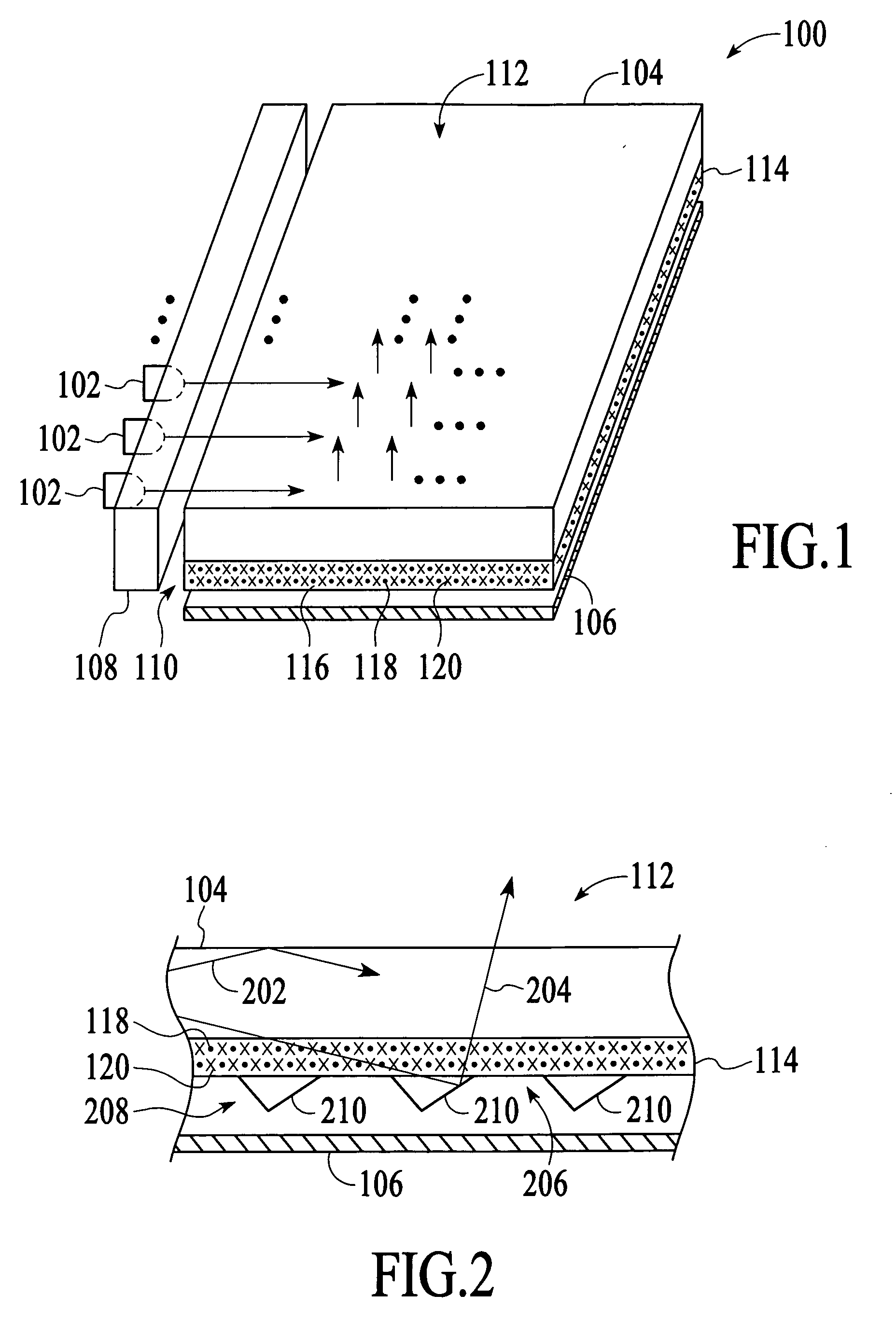
[0019] With reference to FIG. 1, an illumination device 100 in accordance with an embodiment of the invention is described. The illumination device 100 can serve as a backlighting device for a display device that requires external illumination, such as a liquid crystal display (LCD). As described in more detail below, the illumination device 100 utilizes at least one type of quantum dots to provide illuminating light of desired color characteristics through photoluminescence, for example, “white” color illuminating light. The illumination device 100 may also utilize one or more non-quantum fluorescent materials to take advantage of emission characteristics of the fluorescent materials along with the quantum dots to produce illuminating light with increased Color Rendering Index (CRI).

[0020] As shown in FIG. 1, the illumination device 100 includes a number of light emitting devices 102, a light panel 104, a reflector 106 and an optional interface medium 108. The light emitting devic...


PUM


Abstract

A device and method for providing illuminating light utilizes quantum dots to convert at least some of the original light emitted from a light source of the device to longer wavelength light to change the color characteristics of the illuminating light. The quantum dots may be included in the light source, a light panel and / or an optional interface medium of the device.

Description

BACKGROUND OF THE INVENTION [0001] Liquid crystal displays (LCDs) require an external illumination source such as a backlighting device since the LCDs do not themselves emit light. Traditional backlighting devices include a narrow fluorescent tube that serves as a light source to input “white” color light into one of the sides of a light guide panel (also known as “light pipe panel”), which is positioned behind a LCD. The light from the fluorescent tube is internally reflected in the light guide panel and selectively emitted from the top surface of the wave guide panel toward the LCD, providing illuminating light for the LCD [0002] With technological advancements in light emitting diodes (LEDs), the fluorescent tubes in traditional backlight devices are being replaced with LEDs. Some of the advantages of LEDs over fluorescent tubes include longer operating life, lower power consumption, and smaller in size. However, LEDs generally have narrow emission spectrum (approximately + / −10 n...

Claims


Application Information

Patent Timeline
IPC IPC(8): G09G5/00
CPCG02B6/0023G02F2202/108G02F2001/133614G02B6/0055G02F1/133614
Inventor CHUA, JANET BEE YINPAN, KOK CHINNG, KEE YEANTAN, KHENG LENGBAROKY, TAJUL AROSH
Owner EPISTAR CORP
Learn More