Quantum dot white and colored light emitting diodes

a light-emitting diode and quantum dots technology, applied in the field of quantum dots in light-emitting diodes, can solve the problems of poor color control, difficult to produce leds even of a particular desired “pure” single-frequency color, and inability to emit white light, etc., to achieve excellent brightness and color control, good mixing of dots, and manufacturing flexibility

Inactive Publication Date: 2005-05-10
LUMILEDS
View PDF10 Cites 142 Cited by
  • Summary
  • Abstract
  • Description
  • Claims
  • Application Information

AI Technical Summary

Benefits of technology

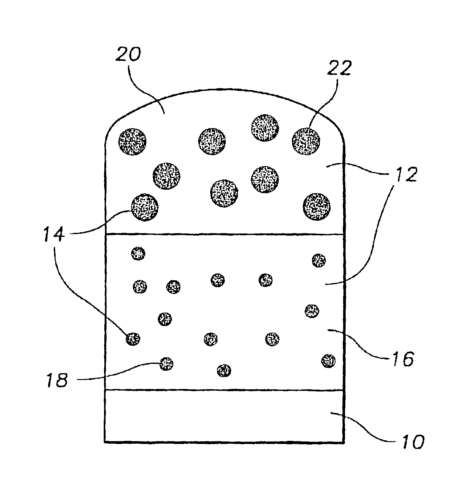
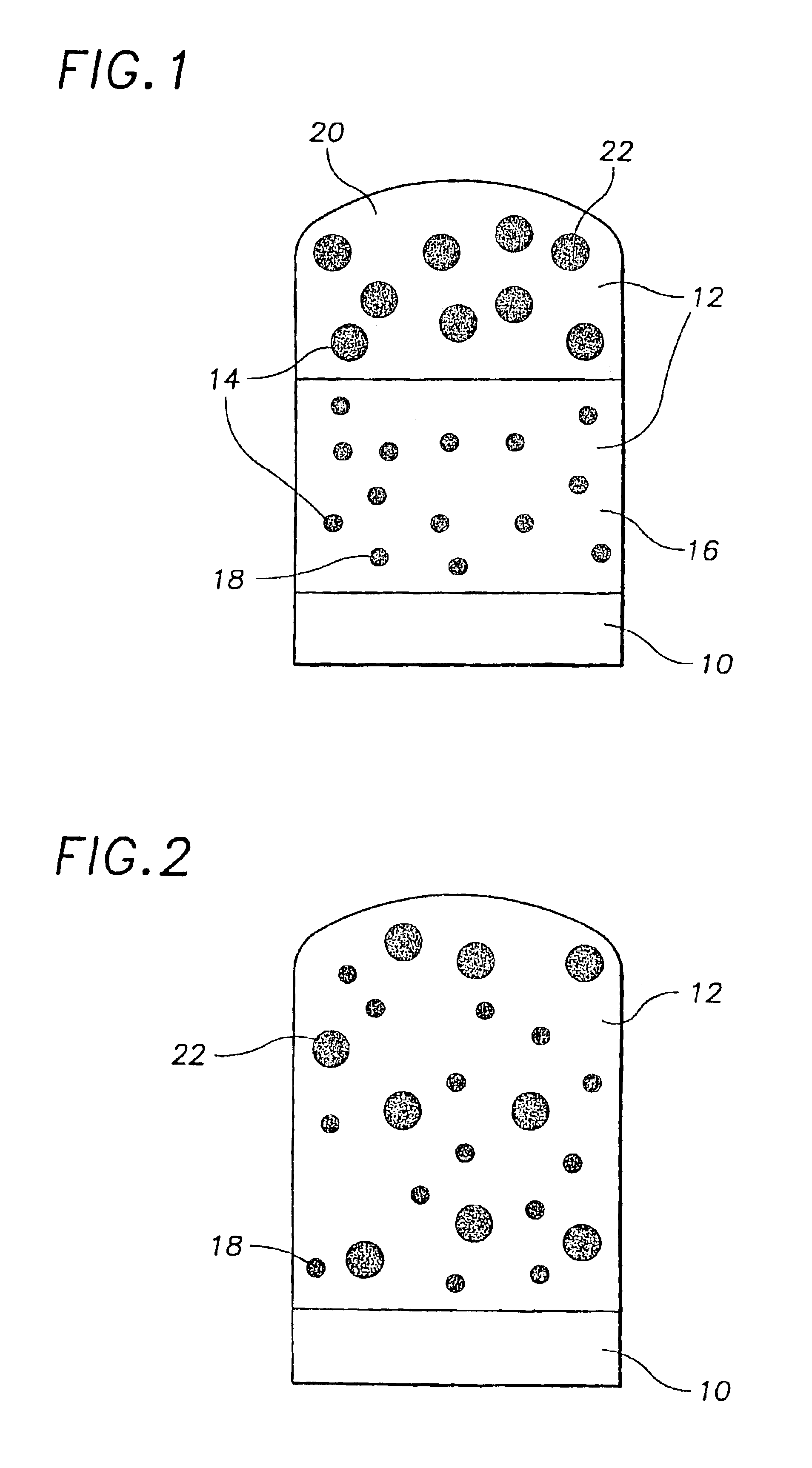
[0039]A further advantage of the present invention is the manufacturing flexibility afforded by the use of multiple populations of quantum dots to achieve both pure and mixed colors of light. “Stock” solutions of different sizes of dots suspended in a monomer or other precursor material can be maintained, and mixed in varying amounts to produce almost any desired color. For example, three suspensions of CdSe quantum dots in a liquid monomer such as styrene could be produced: a first suspension of dots of approximately 5.5 nm diameter (which will luminesce in the red), a second suspension of dots of approximately 4.0 nm diameter (which will luminesce in the green), and a third suspension of dots of approximately 2.3 nm diameter (which will luminesce in the blue). These suspensions function as a kind of “light paint”; by mixing varying amounts of these three suspensions, and polymerizing the resulting mixture, LEDs of a very wide range of colors can be produced using the same manufacturing techniques, varying only the starting materials.
[0040]It will usually be found to be necessary to coat colloidally produced dots with a coating which enables them to be dispersed in the host matrix without flocculation. In the case of dispersal in a polymeric matrix, an oligomer related to the polymer, with a Lewis base at the end of the oligomer which is bound to the dots, has been found to allow good mixing of dots into a monomer solution for polymerization. Particular cases of this type of coating may be found in the Examples. In the case of dispersal into a silica glass or gel, any overcoating which will bind at one end to the dot, and whose other end has an affinity for the matrix, may be used.
[0041]A number of methods of producing quantum dots are known in the art. Any method of producing quantum dots which will fluoresce in the desired colors may be used in the practice of the invention, but it has been found that the particular methods described in U.S. application Ser. No. 08 / 969,302 can be used to produce devices with excellent brightness and color control. That application discloses a method of overcoating dots composed of CdS, CdSe, or CdTe with ZnS, ZnSe, or mixtures thereof. Before overcoating, the quantum dots are prepared by a method yielding a substantially monodisperse size distribution, which is described in Murray, et al., J. Am. Chem. Soc. 115:8706 (1993). An overcoat of a controlled thickness can then be applied by controlling the duration and temperature of growth of the coating layer. The monodispersity of the core dots ensures that the dots will radiate substantially in a pure color, while the overcoat provides a much improved quantum efficiency, allowing the dots to fluoresce more brightly than do uncoated dots.
[0042]The above method can be used to prepare several separate populations of quantum dots, where each population exhibits photoluminescence in a different pure color. By mixing the populations so prepared, a device which fluoresces in any desired mixed color, including white, may be produced. The overcoating on the dots allows the device to produce a brighter light than would be possible using uncoated dots.

Problems solved by technology

Thus, conventional LEDs cannot emit white light, or indeed, light of any “mixed” color, which is composed of a mixture of frequencies.
Further, producing an LED even of a particular desired “pure” single-frequency color can be difficult, since excellent control of semiconductor chemistry is required.
However, color control is poor with this technology, since the colors of the LED and the phosphor cannot be varied.
This technology also cannot be used to produce light of other mixed colors.
However, the maximum theoretical quantum yield for PPV-based devices is 25%, and the color control is often poor, since organic materials tend to fluoresce in rather wide spectra.
Furthermore, PPVs are rather difficult to manufacture reliably, since they are degraded by light, oxygen, and water.
This fabrication technique is suitable for the production of infra-red LEDs, but LEDs in higher-energy colors have not been achieved by this method.
Further, the processing costs of epitaxial growth by currently available methods (molecular beam epitaxy and chemical vapor deposition) are quite high.
Colloidal production of dots is a much more inexpensive process, but these dots have generally been found to exhibit low quantum efficiencies, and thus have not previously been considered suitable for incorporation into light-emitting diodes.
A few proposals have been made for embedding colloidally produced quantum dots in an electrically conductive layer, in order to use the electroluminescence of these dots for an LED, but such devices require a transparent, electrically conductive host matrix, which severely limits the available materials for producing LEDs by this method.
Available host matrix materials are often themselves light-emitting, which may limit the achievable colors using this method.

Method used


Image

  • Quantum dot white and colored light emitting diodes
  • Quantum dot white and colored light emitting diodes
  • Quantum dot white and colored light emitting diodes

Examples


example 1

Quantum Dots in Polystyrene

[0043]A green LED has been constructed according to the principles of the invention described above. The quantum dots used to construct this diode were composed of a CdSe core and a ZnS shell. The absorption and luminescence properties of the quantum dots were primarily determined by the size of the CdSe core. The ZnS shell acted to confine electrons and holes in the core and to electronically and chemically passivate the quantum dot surface. Both the core and shell were synthesized using wet chemistry techniques involving formation of CdSe or ZnS from precursors added to a hot organic liquid.

CdSe Core Synthesis

[0044]16 mL of trioctylphosphine (TOP), 4 mL of 1 M trioctylphosphine selenide (TOPSe) in TOP, and 0.2 mL dimethylcadmium were mixed in an inert atmosphere (nitrogen filled glovebox). 30 g of trioctylphosphine oxide (TOPO) was dried under vacuum at 180° C. for 1 hour, and then heated to 350° C. under nitrogen. The precursor solution was then injecte...

example 2

Quantum Dots in Epoxy

[0050]CdSe / ZnS quantum dots having a 14A core radius were prepared as described in Example 1. 2.5×10⁻³ mmol of dots in TOPO solution were taken, and the dots were precipitated and washed 2 times with methanol. The dots were then redispersed in 0.27 mL (2 mmol) of a capping monomer, 6-mercaptohexanol. In order to effectively disperse the quantum dots in the capping monomer, the solutions were first sonicated for about 10 minutes and then stirred for 2 hours at 50-60° C.

[0051]The quantum dot solution was then further reacted with epoxide monomers. 0.56 mL (2 mmol) of poly[{phenyl glycidylether)-co-formaldehyde] (number average molecular weight=345) and 0.08 mL (0.8 mmol) of diethyltriamine were added to the 6-mercaptohexanol solution. The resulting mixture was thoroughly mixed and placed in a glass tube having an outside diameter of 6 mm and a length of 50 mm. Air bubbles formed during mixing were removed by sonicating for 10 minutes. The glass tube containing the...


PUM


Abstract

An electronic device comprising a population of quantum dots embedded in a host matrix and a primary light source which causes the dots to emit secondary light of a selected color, and a method of making such a device. The size distribution of the quantum dots is chosen to allow light of a particular color to be emitted therefrom. The light emitted from the device may be of either a pure (monochromatic) color, or a mixed (polychromatic) color, and may consist solely of light emitted from the dots themselves, or of a mixture of light emitted from the dots and light emitted from the primary source. The dots desirably are composed of an undoped semiconductor such as CdSe, and may optionally be overcoated to increase photoluminescence.

Description

[0001]This application is a divisional of U.S. application Ser. No. 09 / 167,795, filed Oct. 7, 1998 now issued as U.S. Pat. No. 6,501,091, which claims benefit of U.S. Provisional Application No. 60 / 092,120, filed Apr. 1, 1998. Both of these related applications are incorporated herein by reference in their entirety.[0002]This invention was made with government support under Contract Number 94-00034 awarded by the National Science Foundation. The government has certain rights in the invention.[0003]A portion of the disclosure of this patent document contains material which is subject to copyright protection. The copyright owner has no objection to the facsimile reproduction by anyone of the patent document or the patent disclosure, as it appears in the Patent and Trademark Office patent file or records, but otherwise reserves all copyrights whatsoever.FIELD OF THE INVENTION[0004]The present invention relates to the use of quantum dots in light emitting diodes. The invention further r...

Claims


Application Information

Patent Timeline
Patent Type & Authority Patents(United States)
IPC IPC(8): H01L33/00H01L33/06H01L33/50
CPCB82Y10/00H01L33/06H01L33/502C09K11/883C09K11/02C09K11/565H01L33/504Y10S977/95H01S3/169Y02B20/00
Inventor BAWENDI, MOUNGI G.HEINE, JASONJENSEN, KLAVS F.MILLER, JEFFREY N.MOON, RONALD L.
Owner LUMILEDS
Why Eureka
Try Eureka