Multi-beam image output apparatus and method

a multi-beam image and output apparatus technology, applied in the direction of instruments, printing, measurement devices, etc., can solve the problems of output image jaggy (jitter) and image formed, and achieve the effect of avoiding image jitter

Inactive Publication Date: 2006-05-18
CANON KK
View PDF11 Cites 2 Cited by
  • Summary
  • Abstract
  • Description
  • Claims
  • Application Information

AI Technical Summary

Benefits of technology

[0015] The present invention has been made to overcome the conventional drawbacks, and has as its object to provide

Problems solved by technology

In the multi-beam printer, however, the optical path lengths are different between laser beams, and the scan widths of the laser beams in the main scan direction are inconsistent in the configuration using a single pixel clock generation unit for all laser beams, as shown in FIG. 2.
The inconsistency of the scan widt

Method used


Image

  • Multi-beam image output apparatus and method
  • Multi-beam image output apparatus and method
  • Multi-beam image output apparatus and method

Examples


first embodiment

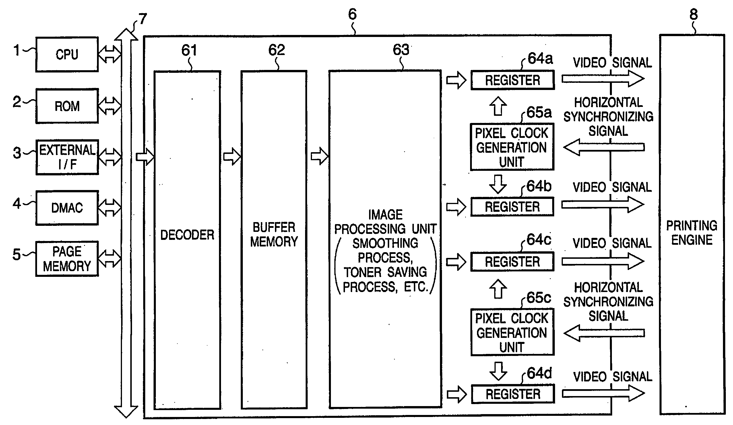
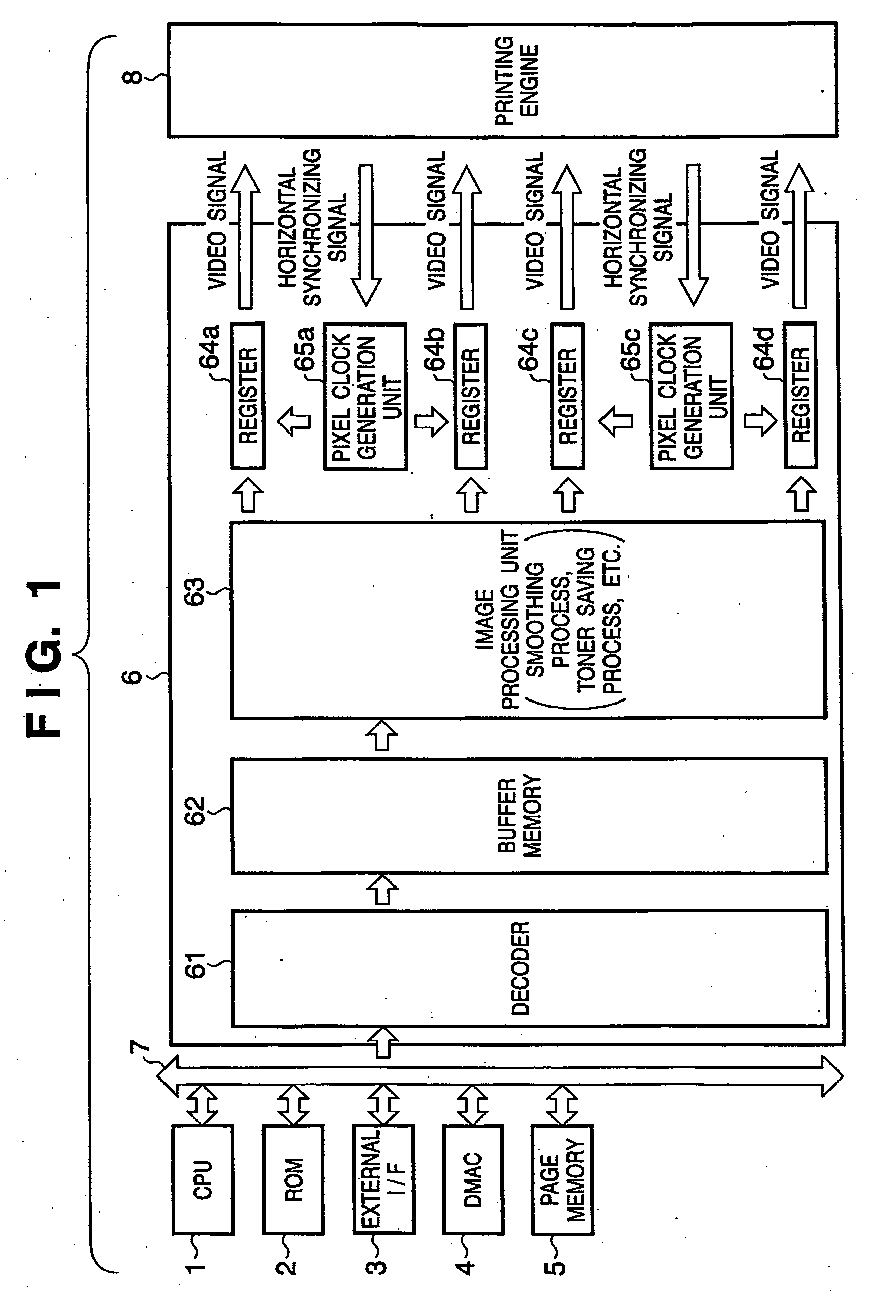
[0032]FIG. 1 is a block diagram showing the configuration of the controller (image output apparatus) of a multi-beam printer according to the first embodiment. As shown in FIG. 1, the controller of the multi-beam printer in the first embodiment comprises a CPU 1, ROM 2, external I / F 3, DMAC (Direct Memory Access Controller) 4, page memory 5, and image output unit 6 which are connected to a system bus 7. The controller is further connected to a printing engine 8.

[0033] The CPU 1 executes a program and the like which are stored in the ROM 2 (to be described later). The CPU 1 controls the overall apparatus, and controls a process of generating print data outputtable to the printing engine 8 on the basis of print data received via the external I / F 3 (to be described later).

[0034] The ROM 2 is a storage device (memory) which stores a process sequence (program) to be processed by the CPU 1, and various data such as font data and template data used for a document process.

[0035] The exte...

second embodiment

[0046] The first embodiment has described a case wherein, for example, the optical path difference between laser beams that form lines of an image is small. However, embodiments according to the present invention are not limited to this. The present invention also incorporates a case wherein a plurality of laser beams having a small difference in image forming timing are generated by the same pixel clock generation unit.

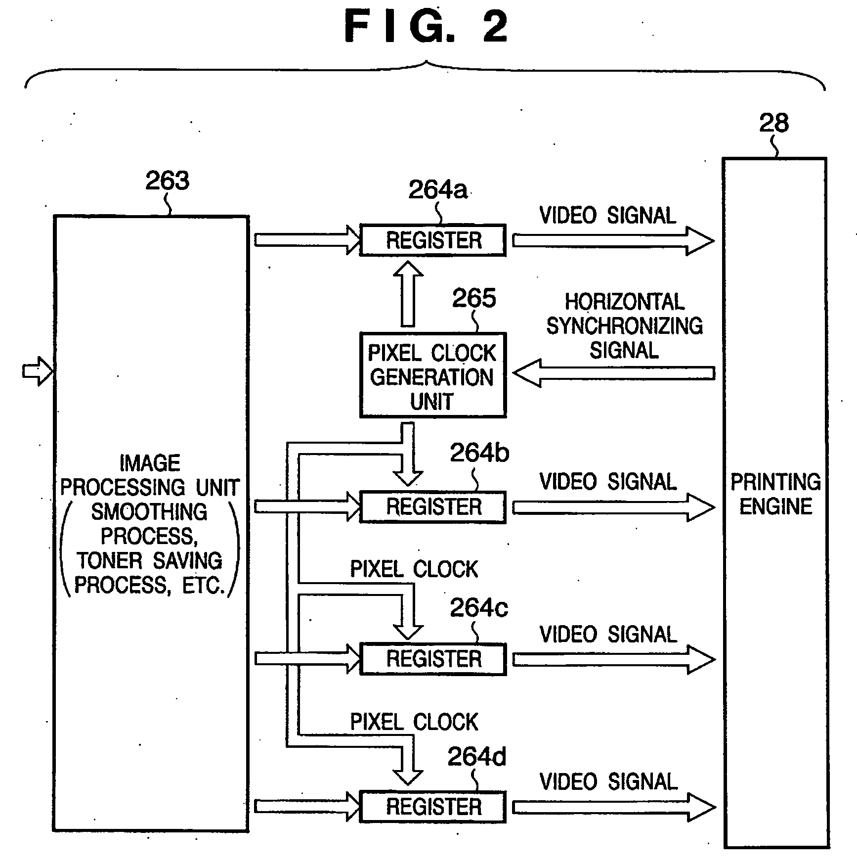
[0047] The second embodiment will explain a case wherein the image forming timings of the first and third lines are almost the same, and those of the second and fourth lines are almost the same, as shown in FIG. 4. In this case, for example, if the first and second lines are operated by the same pixel clock, their image forming start positions are inconsistent, failing to obtain any high-quality image.

[0048] To avoid this, according to the second embodiment, as shown in FIG. 5, registers 364a and 364c for forming the first and third lines of an image are operated b...

third embodiment

[0052] The first and second embodiments have described a configuration using four laser beams, but the present invention is not limited to this. The embodiment can also be applied to a configuration using a predetermined number of laser beams.

[0053] The number of registers for which one pixel clock generation unit outputs a pixel clock can take a desired value for each pixel clock generation unit.

[0054] As has been described above, the present invention can provide an image output apparatus which outputs a high-quality image by using a small number of pixel clock generation units.


PUM


Abstract

An object of this invention is to provide an image output apparatus which outputs a high-quality image by using a small number of pixel clock generation units. This invention provides an image output apparatus which is connected to a printing engine, having a plurality of laser beam control units for controlling a plurality of laser outputs on the basis of input video signals, comprising a plurality of output units which output video signals based on print data to the respective laser beam control units in synchronization with a clock signal; and a plurality of clock control units which are arranged in correspondence with respective groups, that are prepared by grouping said plurality of output units, so as to decrease an optical path difference between laser beams controlled by the corresponding laser beam control unit, wherein each of said clock control units generates the clock signal on the basis of a synchronizing signal generated in image forming operation of the printing engine, and outputs the generated clock signal to output units belonging to a corresponding group.

Description

FIELD OF THE INVENTION [0001] The present invention relates to a multi-beam image output apparatus and method. BACKGROUND OF THE INVENTION [0002] There has conventionally been known multi-beam printers, which scan a photosensitive drum with a plurality of laser beams, perform an image forming process, and thereby achieve printing by laser printer at both high resolution and high speed. <Configuration Using Single Pixel Clock Generation Unit for All Laser Beams>[0003] A schematic configuration using a single pixel clock generation unit for all laser beams will be explained with reference to FIG. 2. FIG. 2 is a block diagram showing a schematic configuration using a single pixel clock for all registers, which generate a video signal in a multi-beam printer for forming an image with four laser beams. [0004] In FIG. 2, an image processing unit 263 receives print data, internally executes image processes such as a smoothing process and toner saving process, and then outputs the res...

Claims


Application Information

Patent Timeline
IPC IPC(8): B41J2/385
CPCH04N1/053H04N2201/04789H04N2201/04781
Inventor MOTOYAMA, MASANAO
Owner CANON KK
Why Eureka
Try Eureka