Word line driving circuit of semiconductor memory device

a technology of driving circuit and memory device, which is applied in the direction of static storage, digital storage, instruments, etc., can solve the problem of bulky layout of the sub-word line driver, and achieve the effect of reducing the layout siz

Active Publication Date: 2006-05-18
SK HYNIX INC
View PDF13 Cites 8 Cited by
  • Summary
  • Abstract
  • Description
  • Claims
  • Application Information

AI Technical Summary

Benefits of technology

[0008] Accordingly, in view of the above layout and complexity problems, a word line driving circuit is disclosed in which a sub-word line driver having only two transistors is constructed, thereby reducing the layout size.

Problems solved by technology

Therefore, the lines of 16 sub-word line driving voltages FX, FXB are required which results in a layout size of the sub-word line driver that is bulky.

Method used


Image

  • Word line driving circuit of semiconductor memory device
  • Word line driving circuit of semiconductor memory device
  • Word line driving circuit of semiconductor memory device

Examples


Embodiment Construction

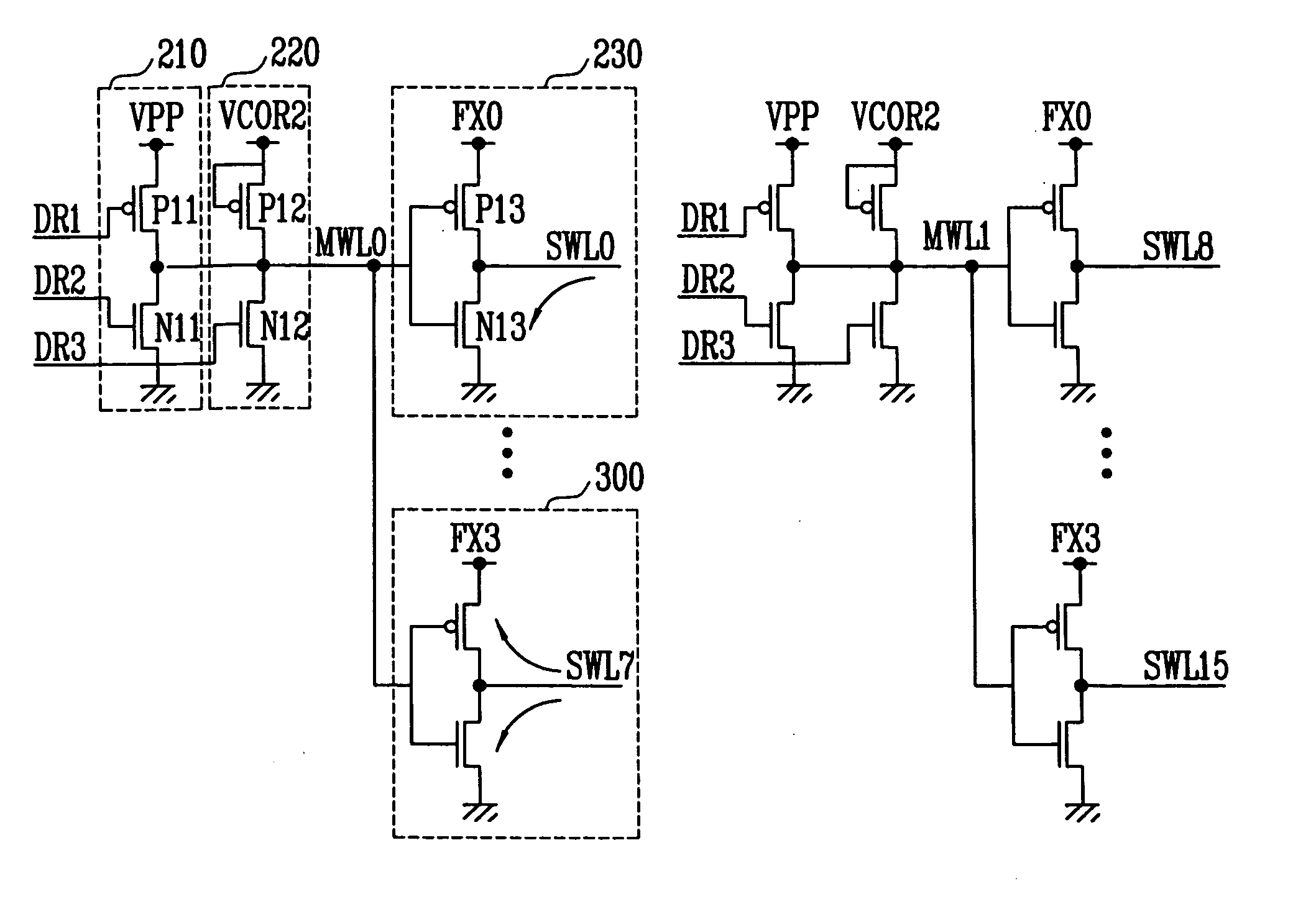
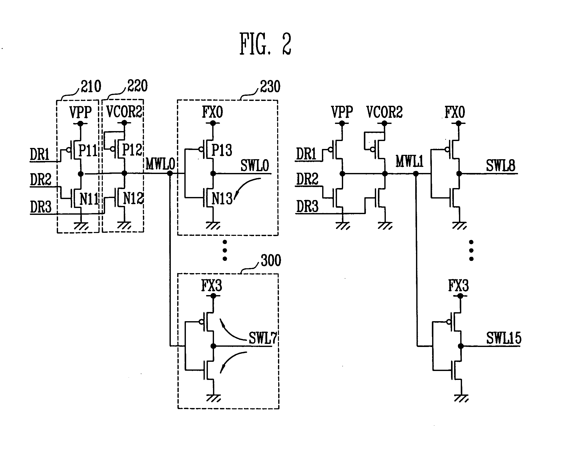
[0015] Now, preferred embodiments will be described with reference to the accompanying drawings. FIG. 2 is a circuit diagram showing a preferred word line driving circuit.

[0016] Referring to FIG. 2, the word line driving circuit includes a main word line driver 210, a floating prevention unit 220, and sub-word line drivers 230 to 300.

[0017] The main word line driver 210 serves to drive a main word line MWL0, and includes one PMOS transistor P11 and one NMOS transistor N11. The PMOS transistor P11 has one end connected to a high voltage VPP, and the other end connected to the main word line MWL0. The PMOS transistor P11 has a gate applied with a driving signal DR1. The NMOS transistor N11 has one end connected to a ground voltage, and the other connected to the main word line MWL0. The NMOS transistor N11 has a gate applied with a driving signal DR2, and thus operates.

[0018] The floating prevention unit 220 serves to leak electric charges (current), which are charged into non-sele...


PUM


Abstract

Disclosed herein is a word line driving circuit in which sub-word lines are prevented from floating by using a sub-word line driver having two transistors. A plurality of sub-word line drivers is connected to one main word line. Each of the plurality of the sub-word lines includes a PMOS transistor and a NMOS transistor serially connected between a sub-word line driving voltage FX and a ground voltage. A floating prevention unit selects the main word line to a level of a threshold voltage using a driving signal having the level of the threshold voltage, thus preventing sub-word lines of a sub-word line driver, where the sub-word line driving voltage FX is off, from floating.

Description

BACKGROUND [0001] 1. Technical Field [0002] A word line driving circuit is disclosed in which sub-word lines are prevented from floating by using a sub-word line driver having two transistors. [0003] 2. Discussion of Related Art [0004]FIG. 1 is a circuit diagram showing a conventional word line driver. The word line driver includes a main word line driver 110, and eight sub-word line drivers 120 to 190. The eight sub-word line drivers 120 to 190 are controlled by one main word line MWL0. [0005] Referring to FIG. 1, the main word line driver 110 includes a PMOS transistor P1 and a NMOS transistor N1. The PMOS transistor P1 has one end connected to a high voltage VPP, and the other end connected to the main word line MWL0. The PMOS transistor P1 has a gate applied with signal DR, and thus operates. The NMOS transistor N1 has one end connected to a ground voltage, the other end connected to the main word line MWL0, and operates according to the driving signal DR. [0006] Each of the eig...

Claims


Application Information

Patent Timeline
Patent Type & Authority Applications(United States)
IPC IPC(8): G11C8/00
CPCG11C8/08G11C8/14
Inventor LEE, JONG CHERN
Owner SK HYNIX INC
Why Eureka
Try Eureka