Method and apparatus for timeout reduction and improved wireless network performance by delay injection

a delay injection and wireless network technology, applied in the field of wireless communication networks, can solve the problems of insufficient delay injection for individual flows, each flow is subject to potential performance-degrading spurious timeouts,

Active Publication Date: 2006-05-18
ALCATEL-LUCENT USA INC
View PDF11 Cites 36 Cited by
  • Summary
  • Abstract
  • Description
  • Claims
  • Application Information

AI Technical Summary

Benefits of technology

[0015] Accordingly, we have realized a technique which avoids spurious TCP timeouts through delay injection which requires no modification of, or requiring access to, the TCP protocol and is consistent with the TCP paradigm. Further, the delay injection is accomplished utilizing any network element along the communications path by operating on TCP packets exchanged across the path.
[0016] More particularly, the aspects of the present invention are directed to the injection of additional random delay or jitter (sometime alternatively referred to herein as “artificial delay”, “injected delay” or “jitter”) at some point in a packet's roundtrip path across a wireless communications network so as to increase the variance in so-called round-trip times (RTT), without significantly increasing the average value thereof. Importantly, in accordance with the principles of the invention, spurious TCP timeouts are reduced, or completely avoided and TCP throughput is increased, through the artificial delay injection without modification of, or requiring access to, the TCP protocol and in a manner, which is consistent with the TCP paradigm. Further, in accordance with an aspect of the invention, the injection of artificial delay is applied on a transaction-by-transaction basis. That is, the decision to inject, or not inject, the artificial delay as well as the value of the injected delay is applied to each TCP connection or TCP flow (i.e., the individual communication link between TCP sender and TCP receiver).
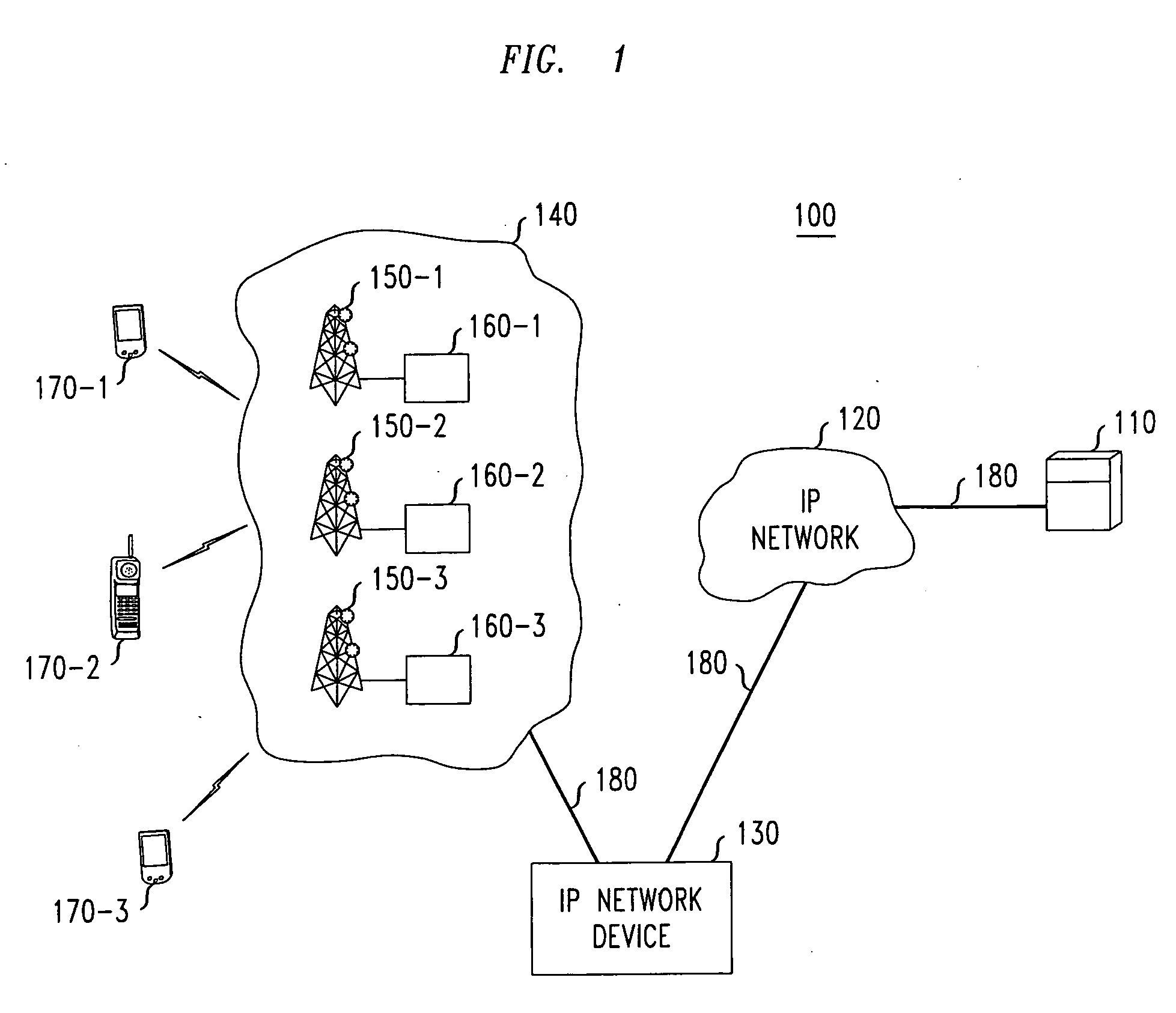
[0017] In accordance with the principles of the invention, the delay injection is accomplished by utilizing any network element (e.g., a router), along the communications path and by operating on TCP packets exchanged across the path. Therefore, the principles of the present invention provide increased control and flexibility over where in the communications network the delay is injected, and allow for delay injection directly at the TCP layer. For example, the network element for injecting delay, in accordance with the invention, may be an intermediary network element along the communications path situated between the ultimate endpoints of the communications link between the TCP sender and TCP receiver. At the network element implementing the delay injection mechanism, the different TCP flows are separated and treated individually and delay is injected according to specified injection parameters for each individual flow. This is particularly important since the TCP congestion control mechanism is applied on a per-flow basis and therefore each flow is subject to potential performance-degrading spurious timeouts. Applying the delay injection on the aggregate stream of packets may result in inappropriate delay injection for individual flows. In addition, different flows may experience different round-trip time statistics and different number of occurrences of spurious timeouts and therefore the appropriate delay injection parameters for optimized per-flow performance could potentially be different.

Problems solved by technology

This is particularly important since the TCP congestion control mechanism is applied on a per-flow basis and therefore each flow is subject to potential performance-degrading spurious timeouts.
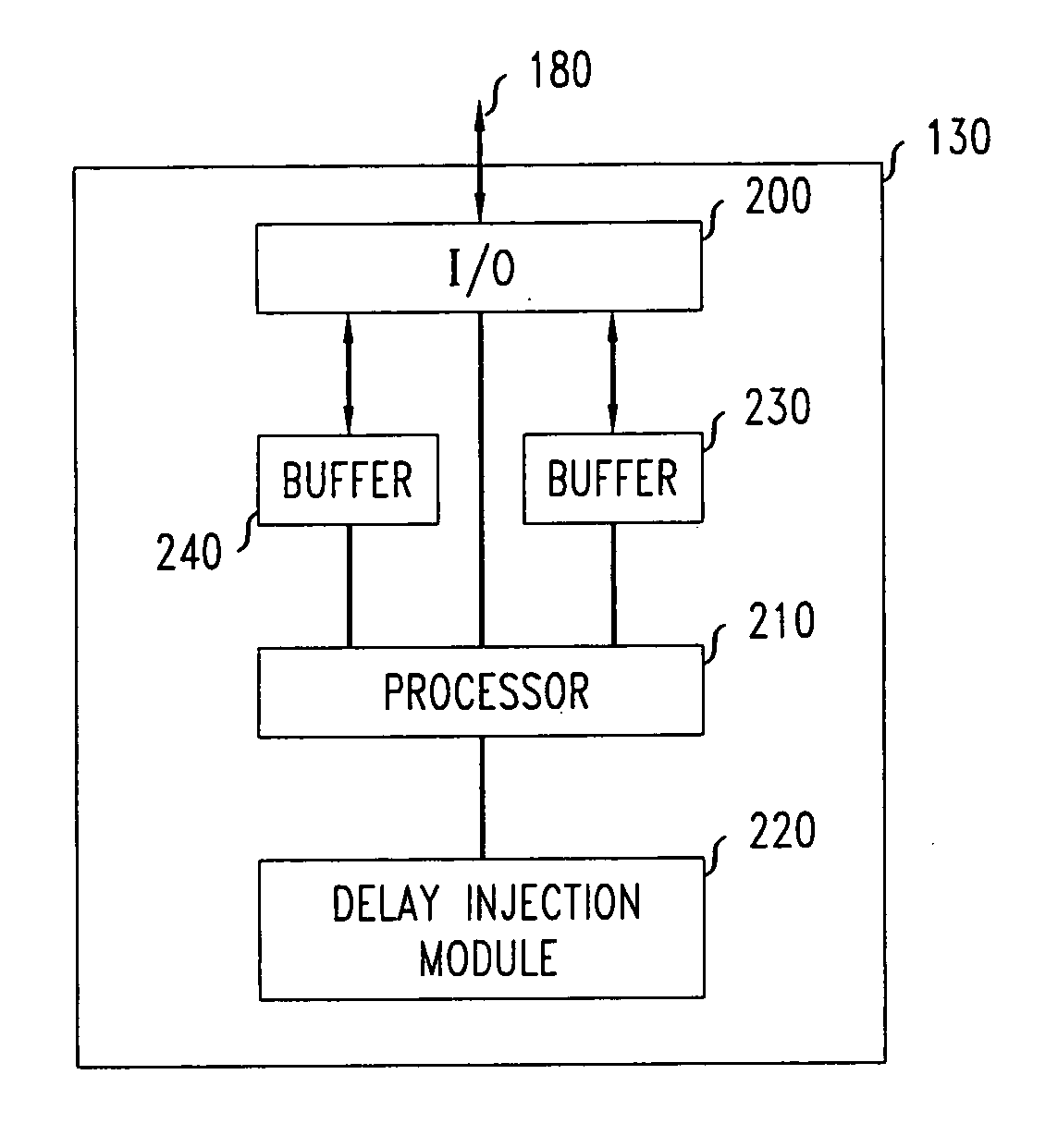
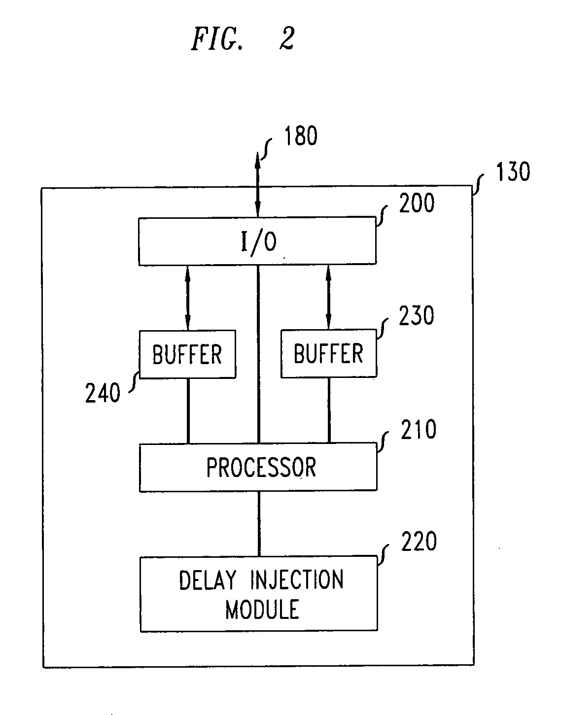
Applying the delay injection on the aggregate stream of packets may result in inappropriate delay injection for individual flows.

Method used


Image

  • Method and apparatus for timeout reduction and improved wireless network performance by delay injection
  • Method and apparatus for timeout reduction and improved wireless network performance by delay injection
  • Method and apparatus for timeout reduction and improved wireless network performance by delay injection

Examples


Embodiment Construction

[0026] While TCP will be well understood by those of ordinary skill in the art, a brief discussion of certain TCP features will be introduced to allow for a better understanding of the various aspects, embodiments and advantages of the present invention. In particular, in order to detect packet or acknowledgement losses, TCP implements a timer which can be viewed as an upper bound on the round-trip time between the sender and the receiver. If an acknowledgement is not received before the timer expires, the corresponding packet is deemed to be lost, the congestion control mechanism is triggered and the packet is retransmitted. As such, the calculation of the timeout threshold is of critical importance (see, e.g., V. Jacobsen, “Congestion Avoidance and Control”, in Proceedings of ACM SIGCOMM, 1988, which is hereby incorporated by reference herein). If we denote by RTT[k] the k-th measurement value of the round-trip time, it will be understood that (in most implementations) only one pa...


PUM


Abstract

A technique for avoiding spurious TCP timeouts through delay injection which requires no modification of, or access to, the TCP protocol itself. More particularly, injection of additional random delay or jitter at some point in a packet's roundtrip path across a wireless communications network is employed so as to increase the variance in round trip times, without significantly increasing the average value thereof. Spurious TCP timeouts are avoided through the artificial delay injection which occurs at a network element along the communications path and without modification of, or requiring access to, the TCP protocol. Further, the injection of artificial delay is applied on a transaction-by-transaction basis. That is, the decision to inject, or not inject, the artificial delay as well as the value of the injected delay are applied to each TCP connection or TCP flow.

Description

CROSS REFERENCE TO PROVISIONAL APPLICATION [0001] This application claims the benefit of U.S. Provisional Application No. 60 / 629,223, filed on Nov. 18, 2004. RELATED APPLICATION [0002] The subject matter of the present application is related to that of U.S. patent application Ser. No. 09 / 665,724, filed Sep. 20, 2000, in the name of inventors J. Cloutier et al. and entitled “Improved Wireless Data Transmission Using Time Out Control”, which is hereby incorporated by reference herein.FIELD OF THE INVENTION [0003] The present invention relates generally to wireless communications networks and, more specifically, to the avoidance of timeouts and improved throughput of such wireless networks. BACKGROUND OF INVENTION [0004] The Transmission Control Protocol (TCP) remains the most widely used transport control protocol across the Internet today. Although TCP was initially designed and optimized for wireline networks, such protocol is increasingly being used over wireless networks primarily...

Claims


Application Information

Patent Timeline
Patent Type & Authority Applications(United States)
IPC IPC(8): G01R31/08G08C15/00H04L12/26G06F11/00H04J3/14H04Q7/00H04J1/16H04L1/00H04J3/06H04L12/56H04L12/28H04W80/06
CPCH04L1/188H04L47/10H04L47/193H04L47/32H04W80/06H04L69/16H04L69/163
Inventor HANER, MARKKLEIN, THIERRY ETIENNELEUNG, KIN K.
Owner ALCATEL-LUCENT USA INC
Why Eureka
Try Eureka