
Temperature-independent external cavity laser

a laser and temperature-independent technology, applied in semiconductor lasers, instruments, optical elements, etc., can solve the problems of difficult reflection filter formation, inability to provide a bandwidth of 50 mbps or more, and cable modems

Inactive Publication Date: 2006-05-18
ELECTRONICS & TELECOMM RES INST
View PDF11 Cites 46 Cited by
  • Summary
  • Abstract
  • Description
  • Claims
  • Application Information

AI Technical Summary

Benefits of technology

[0016] The present invention has been made to solve the above problems, and it is an object of the present invention to provide a temperature independent external cavity laser, designed to have a thin film multi-layered (

Problems solved by technology

Recently, due to widespread application of digital home service systems, it has been predicted that an increased average bandwidth of 100 Mbps per subscriber will be required in near future, and in this case, fiber to the home (FTTH) technologies will gradually replace conventional digital subscriber line (DSL) technologies and cable modem technologies, which cannot provide a bandwidth of 50 Mbps or more.
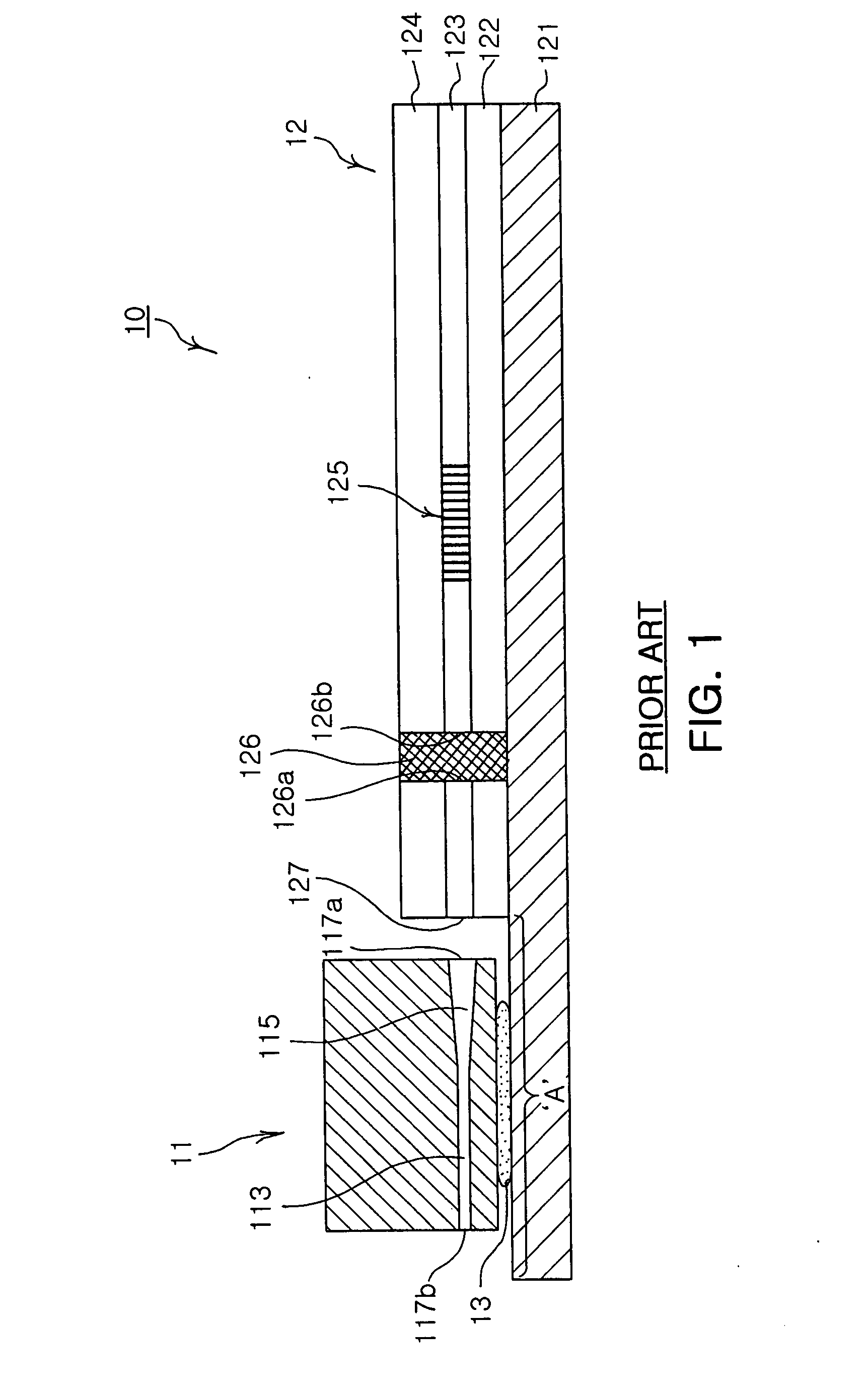
Moreover, due to the phase-mask, it is difficult to form the reflection filter 125 of the Bragg grating structure in an accurate location desired on the planar waveguide platform 12.
Moreover, since the silicon resin 126 is inserted not to a waveguide region but to a free propagation region, additional insertion loss can be generated, and internal reflection can occur due to roughness of side surfaces 126a and 126b where the waveguide is removed, thereby reducing performance of the external cavity laser.

Method used


Image

  • Temperature-independent external cavity laser
  • Temperature-independent external cavity laser
  • Temperature-independent external cavity laser

Examples


Embodiment Construction

[0033] Preferred embodiments will now be described in detail with reference to the accompanying drawings.

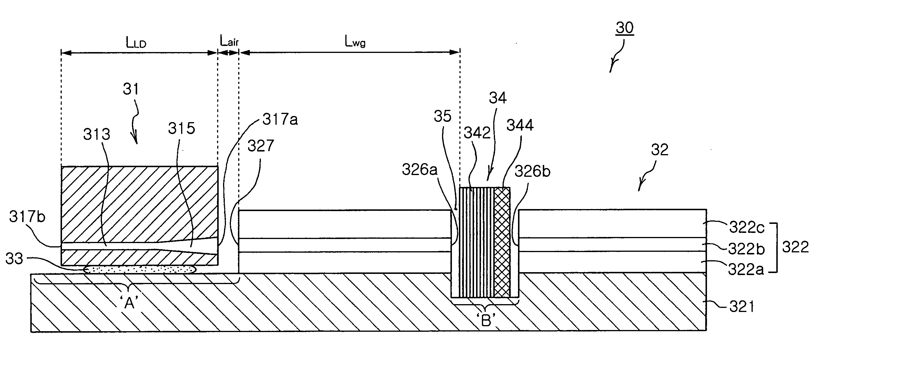
[0034]FIG. 3 is a transverse sectional view illustrating a temperature independent external cavity laser in accordance with one embodiment of the present invention. Referring to FIG. 3, a temperature independent external cavity laser 30 of the present invention comprises: a semiconductor laser diode 31 including an active region 313 to generate light, and at least one light emitting surface 371a to emit the light generated from the active region 313; a planar waveguide platform 32 including a substrate 321, a metallic pattern 33 formed on a predetermined region A of the substrate 321, a waveguide structure 322, and a trench portion 35 formed in a predetermined region B of the waveguide structure 322, in which the waveguide structure 322 comprises a lower clad layer 322a, a core 322b, and an upper clad layer 322c sequentially stacked in this order on a region of the substrate 321...


PUM


Abstract

Hybrid-type external cavity lasers designed to have a semiconductor laser diode mounted on a planar waveguide platform by a flip-chip bonding method. The temperature independent external cavity laser comprises a semiconductor laser diode, a planar waveguide platform, and a thin film multi-layered reflection filter. The semiconductor laser diode includes an active region to generate light, and at least one light-emitting surface. The planar waveguide platform includes a substrate, a metallic pattern formed on a predetermined region of the substrate, a waveguide structure, and a trench portion. The waveguide structure comprises a lower clad layer, a core, and an upper clad layer sequentially stacked in this order on a region of the substrate excluding the predetermined region formed of the metallic pattern. The trench portion has opposite side surfaces on which the core is exposed.

Description

RELATED APPLICATIONS [0001] The present invention is based on, and claims priority from, Korean Application Number 2004-94490, filed Nov. 18, 2004, the disclosure of which is incorporated by reference herein in its entirety. BACKGROUND OF THE INVENTION [0002] 1. Field of the Invention [0003] The present invention relates to hybrid-type external cavity lasers, designed to have a semiconductor laser diode mounted on a planar waveguide platform by a flip-chip bonding method, and, more particularly, to temperature independent external cavity lasers, designed to have a thin film multi-layered (TFML) reflection filter having reflection characteristics independent of temperature variation on a planar waveguide platform, and to provide an optical path constituted by cavities and having a total length, which is constant independent of the temperature variation. [0004] 2. Description of the Related Art [0005] Recently, due to widespread application of digital home service systems, it has been...

Claims


Application Information

Patent Timeline
IPC IPC(8): H01S3/04
CPCG02B5/26H01S3/106H01S5/02252H01S5/02272H01S5/02284H01S5/06804H01S5/1014H01S5/141H01S5/02326H01S5/0237H01S5/02251H01S3/05H01S5/10
Inventor PARK, MAHN YONGKIM, BYOUNG WHI
Owner ELECTRONICS & TELECOMM RES INST
Learn More