High speed binary counter

Active Publication Date: 2006-05-18
MERCURY DEFENSE SYST INC
View PDF6 Cites 3 Cited by
  • Summary
  • Abstract
  • Description
  • Claims
  • Application Information

AI Technical Summary

Benefits of technology

[0026] It is, therefore, an object of the present invention to provide a high speed binary counter. The counter includes a counting first flip-flop

Problems solved by technology

The problem that limits the speed of the counter is the AND gate that grows with the number of bits of the counter and the routing problems associated with transmitting lower order bit information to the AND gates.
The routing and switching delays of these gates limit the speed at which the counter can operate.
High speed binary counters implemented with toggle, or T, flip-flops suffer from the same problems.
The binary counter implemented with the T flip-flops, therefore, suffers from the same limitations as the D flip-flops discussed above.
It may further be implied that any binary counter designed from any type of memory cell (whether any kind of flip-flop or other device) suffers from this same problem of incrementally larger AND gates and greater signal routing requirements as the number of bits grows.
FIG. 4 illustrates, however, the problem with the utilization of a large AND gate.
If the input data changes at or close to the time of the trigger, the flip-flop may not capture the data or may become metastable.
Combinational logic gates

Method used


Image

  • High speed binary counter
  • High speed binary counter
  • High speed binary counter

Examples


Embodiment Construction

[0048] The detailed embodiments of the present invention are disclosed herein. It should be understood, however, that the disclosed embodiments are merely exemplary of the invention, which may be embodied in various forms. Therefore, the details disclosed herein are not to be interpreted as limited, but merely as the basis for the claims and as a basis for teaching one skilled in the art how to make and / or use the invention.

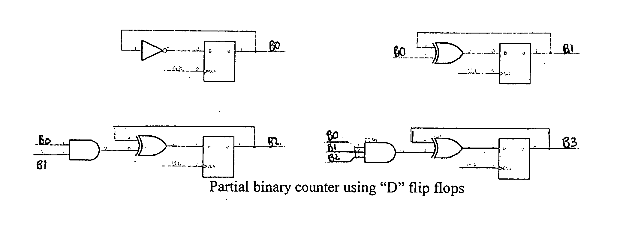
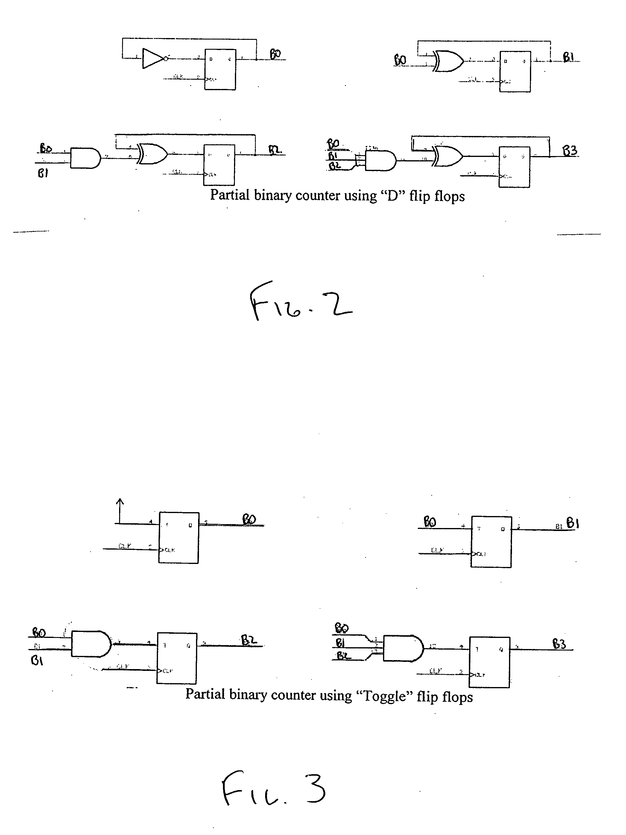
[0049] With reference to the FIGS. 5, 6, and 7, the present high speed binary counter 10 is disclosed. The present high speed binary counter 10 overcomes the limitations of the prior art by providing a binary counter that operates faster, (particularly in programmable logic systems) and operates with greater accuracy. As many of the components employed in accordance with the present invention are substantially similar for the various binary terms, similar numerals will be used when referring to similar components. In addition, the name of the output signal of ea...


PUM


Abstract

A high speed binary counter includes a counting first flip-flop for each binary bit, a single AND gate for each lower order binary bit beyond B0 and B1, and at least two AND gates for each higher order binary bit. The counter also includes an input factor delay second flip-flop. The counter is further provided with a mechanism for redundant least significant terms for lesser order bits.

Description

BACKGROUND OF THE INVENTION [0001] 1. Field of the Invention [0002] The invention relates to a high speed binary counter. More particularly, the invention relates to a high speed binary counter optimized to run faster and provide higher accuracy. This is achieved through the implementation of additional flip-flops and AND gates for higher order input terms of the binary counter. [0003] 2. Description of the Prior Art [0004] With reference to FIG. 1, a comparison of decimal to binary counting is provided. Binary counting is commonly achieved through the use of a binary counter. A binary counter is a digital circuit having a clock input and a number of count outputs that give the number of clock cycles. The output may change either on rising or falling clock edges. The circuit may also have a reset input that sets all outputs to zero when asserted. The binary counter may be either a synchronous counter or a ripple counter. In order to produce a binary counter, a system of sequential l...

Claims


Application Information

Patent Timeline
IPC IPC(8): H03K23/48
CPCH03K23/002
Inventor LEWIS, JAMES M.
Owner MERCURY DEFENSE SYST INC
Why Eureka
Try Eureka