Sintering method and device

a sintering method and a technology for a material are applied in the field of sintering methods and devices, which can solve the problems of inability to obtain a sintered body, change in heating value, and difficulty in sintering the overall material at an even temperature, and achieve the effect of superior sintering ability and uniform quality

Inactive Publication Date: 2006-05-18
NAT INST OF ADVANCED IND SCI & TECH
View PDF2 Cites 43 Cited by
  • Summary
  • Abstract
  • Description
  • Claims
  • Application Information

AI Technical Summary

Benefits of technology

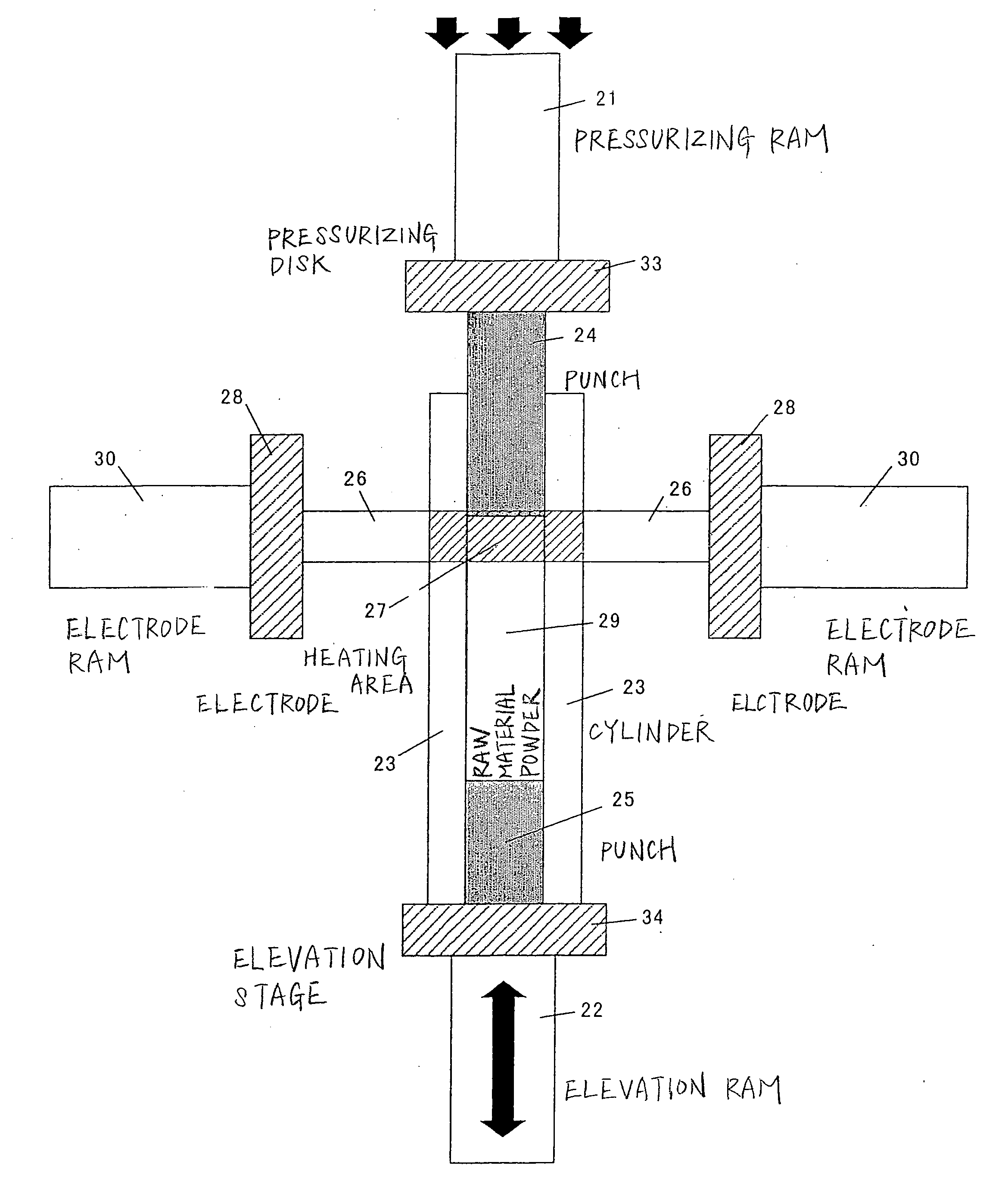
[0012] In view of the foregoing circumstances, an object of the present invention is to provide a sintering method and device that are superior in sintering ability, wherein even if the sintered body is in the form of a long rod or has an uneven cross section, the sintered body is uniform in quality.

Problems solved by technology

Therefore, when manufacturing a sintered product having a long current path such as a rod-shaped material, there is a problem in that it is extremely difficult to sinter the overall material at an even temperature.
Further, with a material in which the cross section of the sintered body is uneven in the lengthwise direction in relation to the current path (i.e., materials with irregular section profiles), since the electrical resistance will change pursuant to the area difference of the cross section perpendicular to the current path, there is a problem in that the heating value will change and an even sintered body cannot be obtained.
Therefore, with the conventional pressurized sintering method employing a direct current, there is a problem in that it is difficult to manufacture a product having an even material quality from a rod-shaped material of a certain length or longer and a stepped material which has an uneven cross section.
Nevertheless, here, since the electrodes and sintered body are subject to the processes at a fixed position, it is not possible to continuously sinter a long material.
Nevertheless, this method is limited to the manufacture of thin plates, and there is a problem in that it is not possible to sinter components of other shapes.

Method used


Image

  • Sintering method and device
  • Sintering method and device
  • Sintering method and device

Examples


example 1

[0059] As shown in FIG. 4, a graphite electrode connection terminal assembly 11 having a thickness of t=10.0 mm was mounted to a mold filled with aluminum as the raw material powder, and the temperature distribution in relation to the distance from the connection terminal assembly 11 upon energization thereof was measured.

[0060] Results of the temperature distribution measured in Example 1 are shown in FIG. 5. It is evident that the temperature becomes lower as the distance from the electrode connection terminal assembly 11 becomes longer. From these results, it is clear that the present invention is able to heat only an arbitrary, limited area up to the sintering temperature.

[0061] Even when the cross section shape (electrical resistance) in the sintering subject material changes, so as long as the heating area is made smaller, the absolute value of the difference of the heating value at the respective positions pursuant to the change in shape will be small. Therefore, if the thi...

example 2

[0063] As shown in FIG. 6, 3.82 g of aluminum having an average grain size of 20 μm was filled in a graphite cylinder mold having an outer diameter of φ30 mm, inner diameter of φ15 mm, and length of L=160 mm, and this is pressed from the top and bottom with a graphite punch having a length of 80 mm.

[0064] A graphite electrode connection terminal assembly (perforated square plate) 11 having a φ30 mm hole in the center and in which the length of one side thereof is 70 mm and the thickness is t=10.0 to 13.2 mm was fitted so as to be attached to the side wall of the cylinder. FIG. 7 shows the cross section of the heating portion in which the thermocouple 12 exists.

[0065] Here, the material of the electrode connection terminal assembly (perforated square plate) 11 used is the same as the material of the cylinder. As a result, the current will flow to the cylinder, and the raw material powder will be heated with energization when the electrical resistance of the raw material powder in t...

example 3

[0074] As shown in FIG. 10, in accordance with the sintering method depicted in Example 2, 9.54 g of aluminum was filled, and a graphite terminal assembly was successively moved from position 1 to position 3 while sintering was effected to the respective positions via current heating.

[0075] Upon examining the density of the aluminum sintered product obtained in Example 3, the relative density showed a value of 99% or more. If the distance to be moved is made longer, the manufacture of an even longer product is possible. Thus, it is evident that a rod-shaped sintered product superior in density can be manufactured with this method.

[0076] Next, as an example of sintering a material having an uneven cross section while setting the heating area, when considering sintering a stepped component as illustrated in FIG. 11, this case shows the sintering of a stepped sintered product formed from a portion having a large diameter and a portion having a small diameter. Foremost, when sintering...


PUM

PropertyMeasurementUnit
lengthaaaaaaaaaa
grain sizeaaaaaaaaaa
thicknessaaaaaaaaaa

Abstract

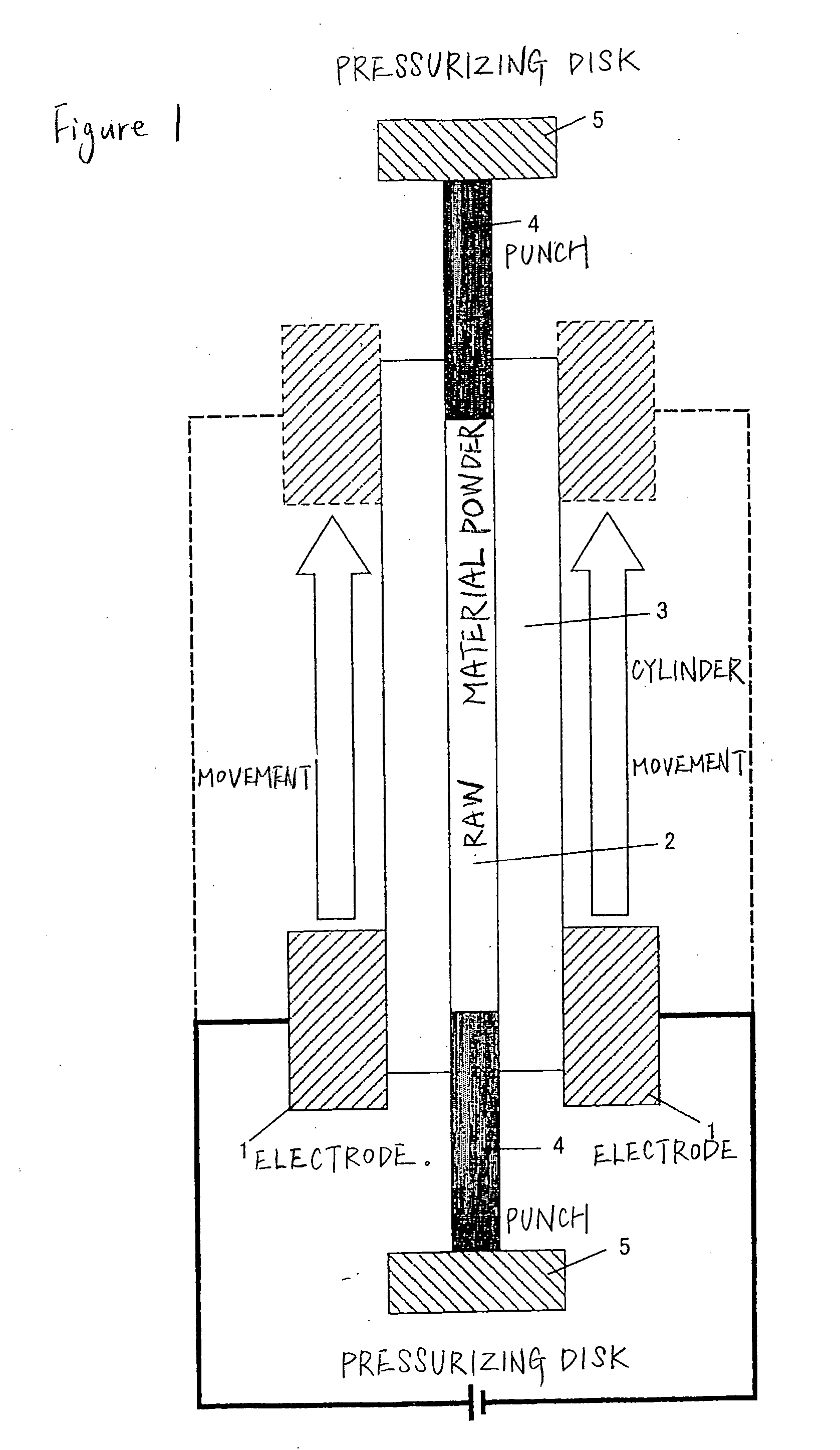
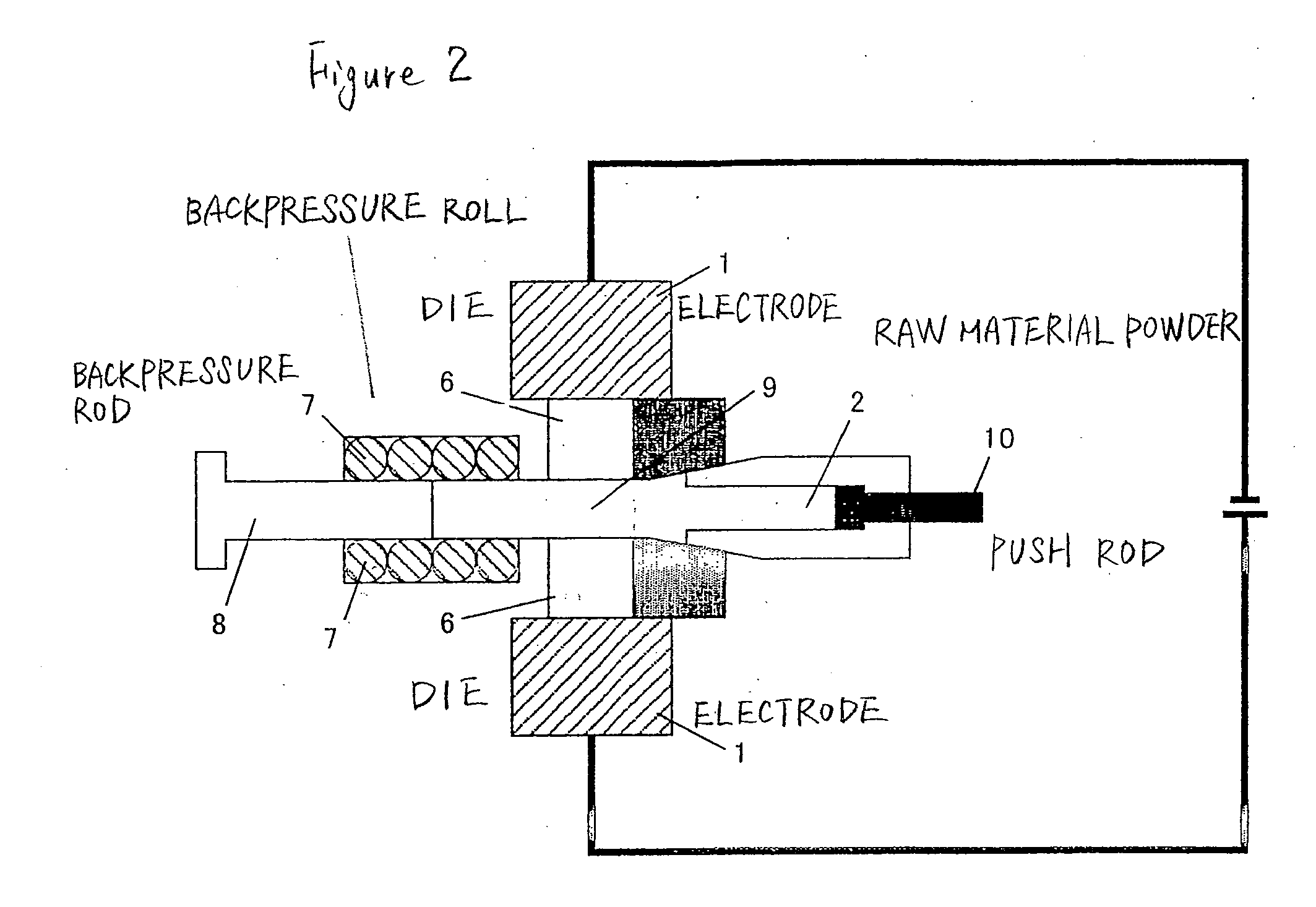
A method of performing direct current pressurized sintering to powder in a mold having a cylindrical molding space, wherein sintering is continuously effected while relatively moving a current portion and a sintering subject; and a sintering device characterized in that the vertical position of the current electrodes is unchanged and the mold and the sintering subject are successively moved with respect to the current electrodes, so as to effect continuous sintering. A sintering method and a sintering device that are superior in sintering ability are provided wherein even if the sintered body is in the form of a long-size rod or has an uneven cross-section, the sintered body is uniform in quality.

Description

BACKGROUND OF THE INVENTION [0001] 1. Field of the Invention [0002] The present invention relates to a method and device for sintering a material in a short period of time by directly applying pressure and current as a result of relatively moving the sintering subject material and heating area while restricting the heating area of the sintering subject material, such as metal and ceramics, to a specific position. The present invention provides a manufacturing method and device suitable for obtaining a sintered body in the form of a long rod or having an uneven cross section. [0003] 2. Description of the Related Art [0004] According to the pressurized sintering method employing a direct current, since it is possible to raise the temperature of the sintering subject material at high speed, the manufacturing time can be significantly shortened in comparison to the conventional sintering method employing atmosphere heating. [0005] Generally, the conventional heat sintering method pursua...

Claims


Application Information

Patent Timeline
Patent Type & Authority Applications(United States)
IPC IPC(8): B22F3/105
CPCB22F3/105
Inventor TADA, SHUJISUN, ZHENG MINGHASHIMOTO, HITOSHIABE, TOSHIHIKO
Owner NAT INST OF ADVANCED IND SCI & TECH
Why Eureka
Try Eureka